Thank you very much for the constructive feedback regarding my posting style, especially the advice on using code tags—I was unaware of that feature, but I have now read the guidelines and corrected my post accordingly. Thank you also for highlighting the distinction between the board types.
I have updated my code and my forum post. I'm posting my complete, current code below using code tags.
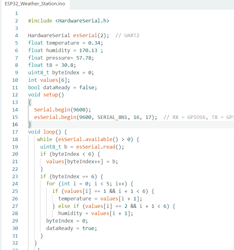
ESP32 DevKitC V4 Code (Receiver):
#include <HardwareSerial.h>
HardwareSerial esSerial(2); // UART2
int temperature ;
int humidity ;
int pressure ;
int t8;
uint8_t byteIndex = 0;
int values[6];
bool dataReady = false;
void setup()
{
Serial.begin(9600);
esSerial.begin(9600, SERIAL_8N1, 16, 17); // RX = GPIO16, TX = GPIO17
}
void loop() {
while (esSerial.available() > 0) {
uint8_t b = esSerial.read();
if (byteIndex < 4) {
values[byteIndex++] = b;
}
if (byteIndex == 4) {
for (int i = 0; i < 5; i++) {
if (values[i] == 1 && i + 1 < 4) {
temperature = values[i + 1];
} else if (values[i] == 2 && i + 1 < 4) {
humidity = values[i + 1]; }
// } else if (values[i] == 3 && i + 1 < 4) {
// pressure = values[i + 1];}
byteIndex = 0;
dataReady = true;
}
}}
// sendTemperatureToNextion();
// sendHumidityToNextion();
// sendPressureToNextion();
// sendT8();
COde F28379D(Transmitter):
//###########################################################################
//
// FILE: Example_2837xDSci_FFDLB_int.c
//
// TITLE: SCI Digital Loop Back with Interrupts.
//
//! \addtogroup cpu01_example_list
//!
SCI Digital Loop Back with Interrupts (sci_loopback_interrupts)
//!
//! This program uses the internal loop back test mode of the peripheral.
//! Other then boot mode pin configuration, no other hardware configuration
//! is required. Both interrupts and the SCI FIFOs are used.
//!
//! A stream of data is sent and then compared to the received stream.
//! The SCI-A sent data looks like this: \n
//! 00 01 \n
//! 01 02 \n
//! 02 03 \n
//! .... \n
//! FE FF \n
//! FF 00 \n
//! etc.. \n
//! The pattern is repeated forever.
//!
//! \b Watch \b Variables \n
//! - \b sdataA - Data being sent
//! - \b rdataA - Data received
//! - \b rdata_pointA - Keep track of where we are in the data stream.
//! This is used to check the incoming data
//!
//
//###########################################################################
//
// $Release Date: $
// $Copyright:
// Copyright (C) 2013-2023 Texas Instruments Incorporated -
http://www.ti.com/
//
// Redistribution and use in source and binary forms, with or without
// modification, are permitted provided that the following conditions
// are met:
//
// Redistributions of source code must retain the above copyright
// notice, this list of conditions and the following disclaimer.
//
// Redistributions in binary form must reproduce the above copyright
// notice, this list of conditions and the following disclaimer in the
// documentation and/or other materials provided with the
// distribution.
//
// Neither the name of Texas Instruments Incorporated nor the names of
// its contributors may be used to endorse or promote products derived
// from this software without specific prior written permission.
//
// THIS SOFTWARE IS PROVIDED BY THE COPYRIGHT HOLDERS AND CONTRIBUTORS
// "AS IS" AND ANY EXPRESS OR IMPLIED WARRANTIES, INCLUDING, BUT NOT
// LIMITED TO, THE IMPLIED WARRANTIES OF MERCHANTABILITY AND FITNESS FOR
// A PARTICULAR PURPOSE ARE DISCLAIMED. IN NO EVENT SHALL THE COPYRIGHT
// OWNER OR CONTRIBUTORS BE LIABLE FOR ANY DIRECT, INDIRECT, INCIDENTAL,
// SPECIAL, EXEMPLARY, OR CONSEQUENTIAL DAMAGES (INCLUDING, BUT NOT
// LIMITED TO, PROCUREMENT OF SUBSTITUTE GOODS OR SERVICES; LOSS OF USE,
// DATA, OR PROFITS; OR BUSINESS INTERRUPTION) HOWEVER CAUSED AND ON ANY
// THEORY OF LIABILITY, WHETHER IN CONTRACT, STRICT LIABILITY, OR TORT
// (INCLUDING NEGLIGENCE OR OTHERWISE) ARISING IN ANY WAY OUT OF THE USE
// OF THIS SOFTWARE, EVEN IF ADVISED OF THE POSSIBILITY OF SUCH DAMAGE.
// $
//###########################################################################
//
// Included Files
//
#include "F28x_Project.h"
//
// Defines
//
#define CPU_FREQ 60E6
#define LSPCLK_FREQ CPU_FREQ/4
#define SCI_FREQ 100E3
#define SCI_PRD ((LSPCLK_FREQ/(SCI_FREQ*8))-1)
//
// Globals
//
//Uint16 sdataA[2]; // Send data for SCI-A
//Uint16 rdataA[2]; // Received data for SCI-A
//Uint16 rdata_pointA; // Used for checking the received data
Uint16 rdata;
Uint16 data;
Uint16 voltage, current;
Uint16 voltage1, current1;
void scib_xmit(int a);
int i;
int index;
int receiving;
Uint16 values[4];
Uint16 byteIndex = 0;
//
// Function Prototypes
//
interrupt void sciaTxFifoIsr(void);
interrupt void sciaRxFifoIsr(void);
interrupt void scibRxFifoIsr(void);
void scia_fifo_init(void);
void scib_fifo_init(void);
void error(void);
//
// Main
//
void main(void)
{
//
// Step 1. Initialize System Control:
// PLL, WatchDog, enable Peripheral Clocks
// This example function is found in the F2837xD_SysCtrl.c file.
//
InitSysCtrl();
//
// Step 2. Initialize GPIO:
// This example function is found in the F2837xD_Gpio.c file and
// illustrates how to set the GPIO to it's default state.
//
InitGpio();
//
// For this example, only init the pins for the SCI-A port.
// GPIO_SetupPinMux() - Sets the GPxMUX1/2 and GPyMUX1/2 register bits
// GPIO_SetupPinOptions() - Sets the direction and configuration of the GPIOS
// These functions are found in the F2837xD_Gpio.c file.
//
// SCIB GPIO Init: GPIO18 = TX, GPIO19 = RX
GPIO_SetupPinMux(19, GPIO_MUX_CPU1, 2);
GPIO_SetupPinOptions(19, GPIO_INPUT, GPIO_ASYNC);
GPIO_SetupPinMux(18, GPIO_MUX_CPU1, 2);
GPIO_SetupPinOptions(18, GPIO_OUTPUT, GPIO_ASYNC);
//
// Step 3. Clear all interrupts and initialize PIE vector table:
// Disable CPU interrupts
//
DINT;
//
// Initialize PIE control registers to their default state.
// The default state is all PIE interrupts disabled and flags
// are cleared.
// This function is found in the F2837xD_PieCtrl.c file.
//
InitPieCtrl();
//
// Disable CPU interrupts and clear all CPU interrupt flags:
//
IER = 0x0000;
IFR = 0x0000;
//
// Initialize the PIE vector table with pointers to the shell Interrupt
// Service Routines (ISR).
// This will populate the entire table, even if the interrupt
// is not used in this example. This is useful for debug purposes.
// The shell ISR routines are found in F2837xD_DefaultIsr.c.
// This function is found in F2837xD_PieVect.c.
//
InitPieVectTable();
//
// Interrupts that are used in this example are re-mapped to
// ISR functions found within this file.
//
EALLOW; // This is needed to write to EALLOW protected registers
// PieVectTable.SCIA_RX_INT = &sciaRxFifoIsr;
// PieVectTable.SCIA_TX_INT = &sciaTxFifoIsr;
PieVectTable.SCIB_RX_INT = &scibRxFifoIsr;
EDIS; // This is needed to disable write to EALLOW protected registers
//
// Step 4. Initialize the Device Peripherals:
//
scia_fifo_init(); // Init SCI-A
scib_fifo_init();
//
// Step 5. User specific code, enable interrupts:
//
// Init send data. After each transmission this data
// will be updated for the next transmission
//
//
// Enable interrupts required for this example
//
PieCtrlRegs.PIECTRL.bit.ENPIE = 1; // Enable the PIE block
PieCtrlRegs.PIEIER9.bit.INTx1 = 1; // PIE Group 9, INT1
PieCtrlRegs.PIEIER9.bit.INTx3 = 1; // PIE Group 9, INT2
IER = 0x100; // Enable CPU INT
EINT;
//
// Step 6. IDLE loop. Just sit and loop forever (optional):
//
while(1)
{
// scib_xmit(1);
// scib_xmit(voltage);
//
// scib_xmit(2);
// scib_xmit(current);
//}
}
//
// error - Function to halt debugger on error
//
//
// sciaTxFifoIsr - SCIA Transmit FIFO ISR
//
interrupt void sciaTxFifoIsr(void)
{
// Uint16 i;
//
// for(i=0; i< 2; i++)
// {
// SciaRegs.SCITXBUF.all=sdataA[i]; // Send data
// }
//sdataA[1]=60;
//sdataA[0]=20;
//
// SciaRegs.SCIFFTX.bit.TXFFINTCLR=1; // Clear SCI Interrupt flag
// PieCtrlRegs.PIEACK.all|=0x100; // Issue PIE ACK
}
//
// sciaRxFifoIsr - SCIA Receive FIFO ISR
//
interrupt void sciaRxFifoIsr(void)
{
// Uint16 i;
//
// for(i=0;i<2;i++)
// {
// rdataA[i]=SciaRegs.SCIRXBUF.all; // Read data
// }
//
//
// SciaRegs.SCIFFRX.bit.RXFFOVRCLR=1; // Clear Overflow flag
// SciaRegs.SCIFFRX.bit.RXFFINTCLR=1; // Clear Interrupt flag
//
// PieCtrlRegs.PIEACK.all|=0x100; // Issue PIE ack
}
interrupt void scibRxFifoIsr(void)
{
// while (ScibRegs.SCIFFRX.bit.RXFFST > 0) {
// Uint16 rdata = ScibRegs.SCIRXBUF.all;
// if (byteIndex < 4){
// values[byteIndex++] = rdata;
// }
//
// if (byteIndex == 4)
// {
// int i;
// for ( i=0; i < 3; i++) {
// if (values[i] == 1 && i + 1 < 4) {
// voltage = values[i + 1];
// } else if (values[i] == 2 && i + 1 < 4) {
// current = values[i + 1];
// }
// }
// byteIndex = 0;
// }
// }
// ScibRegs.SCIFFRX.bit.RXFFOVRCLR=1; // Clear Overflow flag
// ScibRegs.SCIFFRX.bit.RXFFINTCLR=1; // Clear Interrupt flag
//
// PieCtrlRegs.PIEACK.all|=0x100; // Issue PIE ack
}
//
// scia_fifo_init - Configure SCIA FIFO
//
void scia_fifo_init()
{
// SciaRegs.SCICCR.all = 0x0007; // 1 stop bit, No loopback
// // No parity,8 char bits,
// // async mode, idle-line protocol
// SciaRegs.SCICTL1.all = 0x0003; // enable TX, RX, internal SCICLK,
// // Disable RX ERR, SLEEP, TXWAKE
// SciaRegs.SCICTL2.bit.TXINTENA = 1;
// SciaRegs.SCICTL2.bit.RXBKINTENA = 1;
// SciaRegs.SCIHBAUD.all = ((uint16_t)SCI_PRD & 0xFF00U) >> 8U;
// SciaRegs.SCILBAUD.all = (uint16_t)SCI_PRD & 0x00FFU;
// SciaRegs.SCICCR.bit.LOOPBKENA = 1; // Enable loop back
// SciaRegs.SCIFFTX.all = 0xC022;
// SciaRegs.SCIFFRX.all = 0x0022;
// SciaRegs.SCIFFCT.all = 0x00;
//
// SciaRegs.SCICTL1.all = 0x0023; // Relinquish SCI from Reset
// SciaRegs.SCIFFTX.bit.TXFIFORESET = 1;
// SciaRegs.SCIFFRX.bit.RXFIFORESET = 1;
}
void scib_fifo_init()
{
ScibRegs.SCICCR.all = 0x0007; // 1 stop bit, No loopback
// No parity,8 char bits,
// async mode, idle-line protocol
ScibRegs.SCICTL1.all = 0x0003; // enable TX, RX, internal SCICLK,
// Disable RX ERR, SLEEP, TXWAKE
ScibRegs.SCICTL2.bit.TXINTENA = 0;
ScibRegs.SCICTL2.bit.RXBKINTENA = 1;
ScibRegs.SCIHBAUD.all = 0x0002;
ScibRegs.SCILBAUD.all = 0x008B;
ScibRegs.SCICCR.bit.LOOPBKENA = 0; // Enable loop back
ScibRegs.SCIFFTX.all = 0xC022;
ScibRegs.SCIFFRX.all = 0x0022;
ScibRegs.SCIFFCT.all = 0x00;
ScibRegs.SCICTL1.all = 0x0023; // Relinquish SCI from Reset
ScibRegs.SCIFFTX.bit.TXFIFORESET = 1;
ScibRegs.SCIFFRX.bit.RXFIFORESET = 1;
}
void scib_xmit(int a)
{
while (ScibRegs.SCIFFTX.bit.TXFFST != 0) {} //#0 no empty yet not transmit
ScibRegs.SCITXBUF.all=a;
}
//
// End of file
//