You need a kickback suppression diode (1N4004) in parallel with the motor (white band on diode toward motor + (positive) connection), other end of diode toward motor - (negative).
1N4004 diode
JCA34F, thank you for your reply. That information was very helpful. I will try it and let you know.
How is the Arduino powered? You can not power it through the voltage sensor.
jCA34F, Arduino is powered from my notebook USB cable. But I plan to power it from a 9V Crona when the robot is completed. You can see the actual scheme in the post #9.
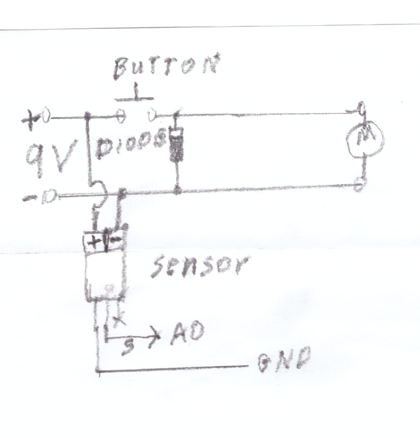
You can power the Arduino from 9V through the barrel jack or the VIN pin but running a motor from the same 9V battery is not a good idea, The motor will deplete the battery pretty fast. Do not try to power the motor from the Arduino 5V pin. Also, the way you have the voltage sensor connected doesn't look right to me.
jCA34F, yes. I already fixed that in my previous post before you wrote your last message. You just didn't see that. And my motor, it does not have "+" and "-". It just rotates back and forth when I exchange the wires. Do I still need to use the diode in such a case?
The diode cathode (end with white band) must ALWAYS connect to the positive voltage, otherwise, it will be a short circuit.
Ok, I see.
I will try using another scheme as well and let you know.
I have tried this option, but it didn't solve the problem. It still persists without any change, but thank you for that substantial knowledge about kickback suppression. I am going to try another scheme which you have provided in the post #20, but would you, please, tell me how it will change when adding a motor to the power supply. A rough sketch of yours would be just great.

Post #20 was by @xfpd, give me some time to make a drawing.
In general, you can't power a motor through a breadboard.
ZX80, Thank you for your reply. The point is that I already do and it works, but stops Arduino serial monitor. Would you, please, explain how can I measure the energy state of the whole robotic system? I mean I have a power supply which as I know provides some energy, but I just want to see its current state excluding motor, relays, etc. I just need to output on the display how much it has for the time being with all those parts involved. And why should I not power a motor using a breadboard? And, well, how should I do that?
And then all that is going to be connected to motor drivers and so on. And, maybe, I do have a problem with a breadboard because of the motors. Is there any tutorial on how I can use it all together and separately, and what is the most important thing, correctly?
Yes, sure. I am not in a hurry. It's been a plenty of time and this issue with kickback supression - it is said to be of critical importance in electronics. I would be very glad if we could solve it, because it's for the second time I can't move further with my project about electromobile. It's a pity, all that works separately, but when it comes to a larger robotic system it just starts to make various conflicts and I am just not able to control all that at such a difficult level.
The purpose of the diode across an inductive load like a solenoid, relay coil or motor winding is to clamp the "kickback" voltage so it doesn't cause interference with sensitive circuits. When current is flowing through a coil, a magnetic field is built up around the coil. When the current is interrupted, the field suddenly collapses, the magnetic lines of force cutting across the coil windings generate a rapidly rising voltage of opposite polarity that can exceed hundreds of volts across the switch contacts. The parallel diode is now forward biased and effectively shorts the current to the now negative end of the coil, clamping the voltage to about 7 volts (for a silicon diode).
https://en.wikipedia.org/wiki/Electrical_reactance#Inductive_reactance
JCA34F, thank you so much. I will try to apply it and as soon as it's ready let you know about the outcome.
Unfortunately, the problem still persists and I still couldn't solve it. Maybe, it's just impossible to measure a voltage in the mentioned case or I need to use other tools for doing that. If there are any other ideas (schemes, methods, tools or anything which may help) I would be very glad to hear your advice and thank you all for your kind attention and support.
It's strange, but when I use LCD display for output this problem with serial port disappears. There are 3 ways I can power Arduino in this case: USB cable, power jack and vin. This problem shows up again if I power Arduino with power jack (there are plenty of uknown symbols on the screen of LCD 2004 in such a case). And what is more, it shows 10-11 volts before I start the motor instead of 9. And when I use USB or vin it shows 9.52V (full battery pack, 6 x AA).
Starting to look like your Leonardo is damaged.