Servo and stepper triggering with limit switches

Good Afternoon All,

I'm trying to build this little 4-8mm diameter tubing cutter using a stepper to feed the material and a servo to act as a cutter. At first, I was going to determine the lengths by adjusting the stepper rotations in the loop BUT I might have to cut several different lengths. That brought me to the idea of using a limit switch to set the length of the tube and the stepper just rotates infinitely until that triggers it to stop and the servo to cut.
the other switch is there just so nothing starts rotating unless material is actually in place.

Would this work? All of this would easily work using motors, relays and limit switches but I thought its be a great opportunity to learn how to use the Arduino in an actual problem I have.

As far as the code, i tested some preliminary control using a SG90 and a 28BYJ-48 from the elegoo kit and it worked fine, just power lacking, hence why I'm using the items drawn. All without the limit switches.

I thought of using the limit switches as analog inputs and setting them as "if" triggers during the loop. Like once feed switch triggers it can run the feed stepper infinitely until the length switch triggers, powers servo to cut the tube, delays for a second and resets the loop.
BUT, I keep reading you're not supposed to use limit switches as analog inputs so...

in short, would the electronics fit this purpose and two CAN it be programmed to run like described?

Sorry for the long post and THANKS!

Yes, it should work. BUT! the key is getting the physical part done before selecting any of the electrical components. That way you know the torque and movement requirements for what you need to purchase.
I am including a picture of a commercial wire cutter I had to baby sit to keep it working. The BIGGEST problem and you will have the same problem, was to make the feed stepper grip the wire, or in your case, the tubing. The drive wheel on the wire feeder was coated with very fine, very sharply pointed material. I have never discovered what it was. But, it was always able to get a grip on wire insulation, even Teflon.
I had to replace the idler/press roller because people had run the machine without wire and the feed wheel had worn the rubber tire on the press roller.
wire
May I suggest you not use a servo to cut the tubing, but use the same mechanism the wire cutter used. It had a solenoid pulling the blade to cut the wire. A large value capacitor was charged and the suddenly discharged in to the solenoid coil to quickly chop the wire. The cut end was then fed out of the machine as the new wire length was being fed into the machine.
Good luck!

1 Like

I’ll have to look it up. I did see someone make a brass wire cutter and it behaved rather well.

Tubing itself is flexible pvc (8mm) and ptfe (4mm). I cut em by hand with the same small tube cutter they sell for 3d printing supplies (reason why i thought of using the 25kg servo. Move the pivot point a little further and the blade will slice easy.

I'd be way easier to trigger a solenoid tbh. The extruder at work uses a solenoid valve and a pneumatic bottle to clip similar ones. Just looks a little bulky for me to print the frame for it :sweat_smile: but yeah, much easier to handle. The limit switch would just close the valve. Gotta buy a compressor tho.

With a servo id just adjust travel by changing angles on it and the thing itself doesn't take much space

As far as the stepper to drive it, you are correct, the 8mm ones deform and itll be a nightmare. Might use a ratchet looking gear to kinda grip the tubing and push forward like 3d printer filament.

Have a friend with a metalworking shop make a knurled wheel for the stepper motor.

Yeah i can lathe one. Do have to find the sweet spot where it grips but doesn't marr/damage the tubing

How about a rubber wheel from a toy car?

The ones lego cars used to have that look like they have flaps ought to work. Some trial and error might be needed

Probably a standard abrasive coating, like in a diamond file perhaps?

Ok so I've managed to wire everything together without limit switches or the step down modules (wanna test movement before load)
Here's what it looks like:


image0

The CNC shield + DRV8825 is totally overkill since I'm only using one axis/stepper and wont use GRBL but figured it'd be the less easy for me to mess up :smiley:
Set the adequate voltage on the driver.
Must add i have no idea whatsoever about coding (or electronics) so everything ive done here is based off of the tutorials and some tweaking about...
That said, I'm able to get the motor to spin 1 turn (or up to 5 times) clockwise and then move the servo to cut.
Don't really know why i can only go up to 5 but that's not important since the plan is to make it spin continuously until a limit switch is triggered.

Problemssssss:

  1. No idea where to place the Switches... figured pins 10 (Y+ End Stop "Servo Cut") and 9 (X+ End Stop "Hose loaded so cycle start") nor how to code em.
  2. After I figure how to identify and call for those two... How do i get the Stepper to start infinite rotation when 9 is triggered until it reaches 10???
#include <Servo.h>
Servo cutservo;

#define EN        8  
#define X_DIR     5  //Direction pin
#define X_STP     2 //Step pin

//DRV8825
int delayTime=30; //Delay between each pause (uS)
int stps=6400;// Steps to move

void step(boolean dir, byte dirPin, byte stepperPin, int steps)
{

  digitalWrite(dirPin, dir);
  delay(100);

  for (int i = 0; i < steps; i++) {

    digitalWrite(stepperPin, HIGH);

    delayMicroseconds(delayTime); 

    digitalWrite(stepperPin, LOW);

    delayMicroseconds(delayTime); 

  }

}

void setup(){
  cutservo.attach(11);
  cutservo.write(150);// Return position
  pinMode(X_DIR, OUTPUT); pinMode(X_STP, OUTPUT);
  pinMode(EN, OUTPUT);
  digitalWrite(EN, LOW);

}

void loop(){

// if Material Loaded Lim Switch 9 activated
  step(false, X_DIR, X_STP, stps); //X, Clockwise

//When Servo Cut Lim Switch 10 
  cutservo.write(30);// Cut Hose
  delay(500);
  cutservo.write(150);// Return Cutter
  delay(1000);


}

This is how the pins are mapped between the Uno and the CNC shield V3.
cnc shield Uno pins

Don't power the servo from the Uno 5V. It will need its own power supply, one that can provide at least 1A. It may "work" unloaded, but put a load on it and your Uno might start resetting unexpectedly.

What is the servo driver part number? Did you set the coil current limit according to the relevant procedure? That is very important.

Robin2's simple stepper code tutorial may be of interest.

The Stepper library is fine for testing, but the AccelStepper library or the MobaTools library can work better. Both libraries have examples to help in their use.

Don't attempt to power the servo from the pin labelled "5V" on the UNO. :astonished:

That pic helped with finding out what pins 9, 10 and 11 were so id have a signal for the servos and the limit switches.

I know powering the servo with the Uno 5V is bad, for some reason i cant get the elegoo power module to feed/trigger it so in the desperation i just triggered it with the Uno. Have a couple of step down modules i'll feed the 12 VDC wires to and just go 5V for the Uno (since its not going to be connected to a computer while in use) and 6-7 V to the servo.

servo driver is DRV8825 and i set the Vref (.75V) to half the rated current for the motor (1.5 A) which is what some tutorials suggested.

i'll dive into the links you sent and try to learn some :smiley:

Thanks!

After A LOT of tweaking [mainly cause I don't know what I'm doing AND the cnc shieldS (emphasis on the S here) were duds] I've managed to fix the new nano cnc shield and get the thing running.


There is an "appropriate" board on its way.

Changed the set up a bit from where it started so I'm not sure if i have to start a new thread or keep it on this one.

Mainly changed to the board and shield from previous because i just couldnt get the program running how i wanted with the shield and it turns out the board itself seemed to be the problem (just like this one... wont name the brand tho)

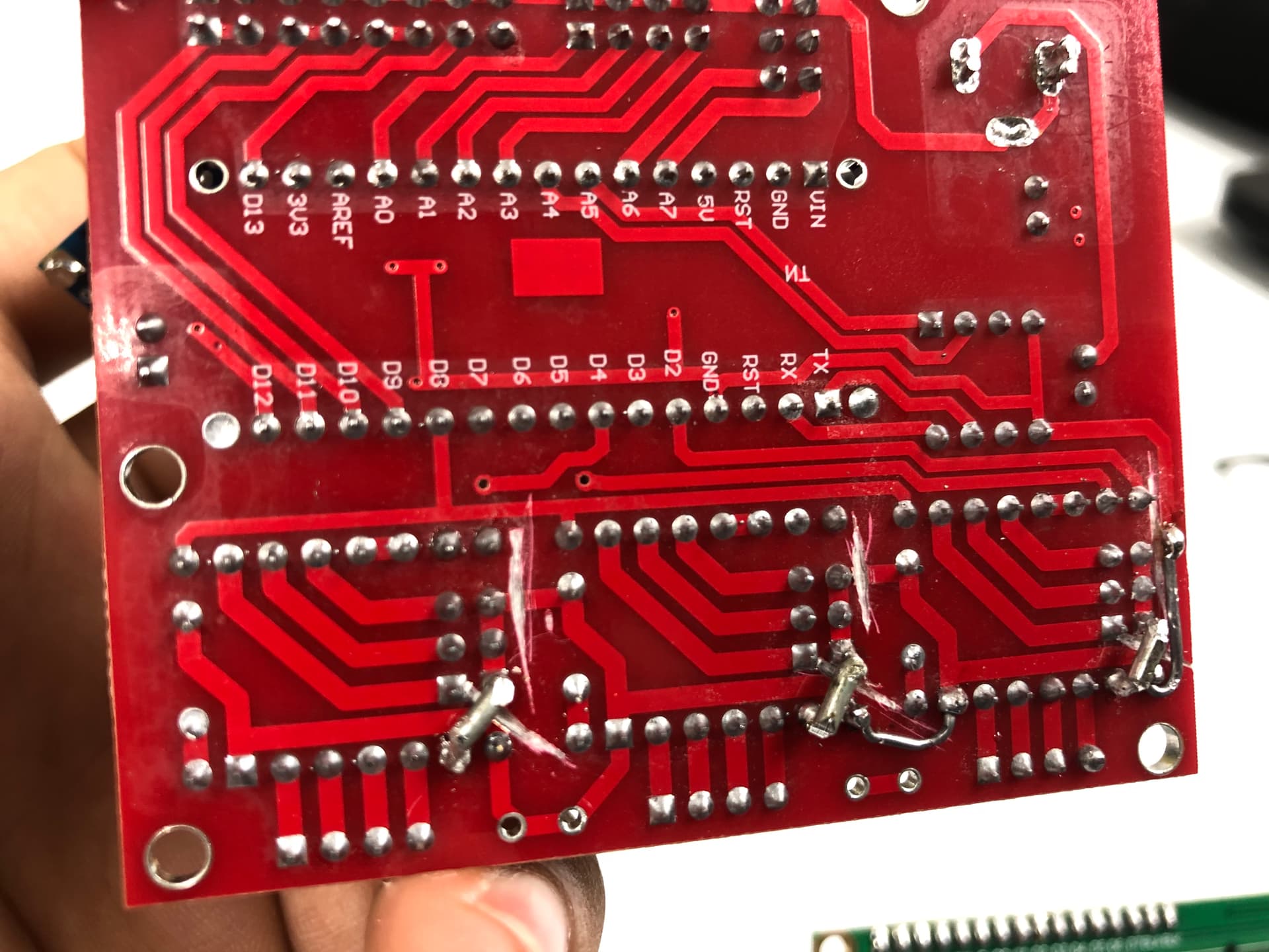
Dunno how to post a video here so a pic it is:

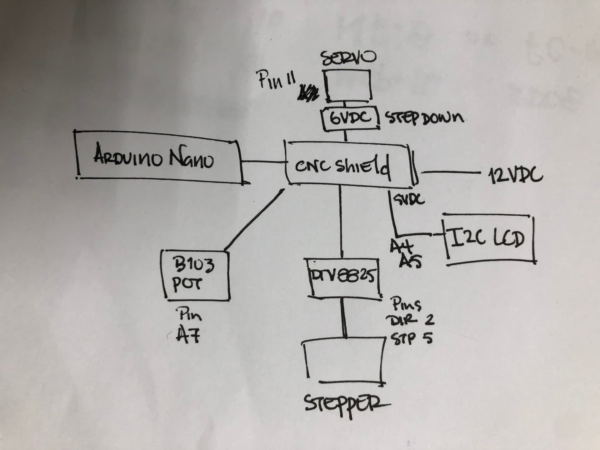
Although it is working, the value on the LCD fluctuates randomly from about +/- 0.06. Could be the pot acting up so I'll replace it with another 10k Pot (B103) i have in the elegoo kit i bought.

The WORST part though is it often stops the cycle (right before refreshing the value on screen) as if its trying to process what's going on and then starts back up randomly (usually about 1 to 5 seconds).No idea if my frankencode is just asking too much of it so I figured I'd ask.
The 5v outputs for the LCD and the Pot are connected directly to the CNC Shield. Main power comes from a wall wart 12VDC 5A.

I did try going the encoder route (ky-40) instead of a potentiometer but could not get the thing to stay put on a single value and was reeeeeally discouraging me.

FrankenCode:

#include <Servo.h>
#include <Wire.h>
#include <LiquidCrystal_I2C.h>
LiquidCrystal_I2C lcd(0x27,16,2); // set the LCD address to 0x27 for a 16 chars and 2 line display
Servo cutservo;

//Stepper config
#define EN        8  
//Direction pin (should be 5)
#define X_DIR     2 
//Step pin (should be 2)
#define X_STP     5

//DRV8825
int delayTime=35; //Delay between each pause (uS)
int stps=6400;// Steps to move for one turn
int val = 0;
int previous = 0;
int long stpval = 0;
int long dispval = 0;

void step(boolean dir, byte dirPin, byte stepperPin, int steps)

{

  digitalWrite(dirPin, dir);
  delay(10);
  for (int i = 0; i < steps; i++) {
    
    digitalWrite(stepperPin, HIGH);
    delayMicroseconds(delayTime); 
    digitalWrite(stepperPin, LOW);
    delayMicroseconds(delayTime); 
  }
}

void setup(){
 
  cutservo.attach(11);
  cutservo.write(30);// Start/Return servo position
  pinMode(X_DIR, OUTPUT); 
  pinMode(X_STP, OUTPUT);
  pinMode(EN, OUTPUT);
  digitalWrite(EN, LOW);

  Serial.begin(9600);
  // Print a message to the LCD.
  lcd.begin();
  lcd.backlight();
  lcd.setCursor(5,0);
  lcd.print("Length:");
  lcd.setCursor(6,1);
  lcd.print(dispval/100.00);
 
}

void loop(){
 val = analogRead(A7);
 if ((val > previous+5) || (val < previous-5)){ //Lower some of the analog fluctuation but didnt work.
int long stpval=map(val,0,1023,5600,14400); //Change values on Pot to amount of microsteps for a range of turns.
int long dispval=stpval / 20.382 ; // Convert to length (using a higher number just so i can divide later and get decimals on LCD)
 
  lcd.begin();
  lcd.backlight();
  lcd.setCursor(5,0);
  lcd.print("Length:");
  lcd.setCursor(6,1);
  lcd.print(dispval/100.00);//Must divide by at least 10.00 to get the decimal points (for some reason)

  step(true, X_DIR, X_STP, stpval); //X, (True)CClockwise, (false) Clockwise
  previous = val;

  cutservo.write(150);// Cut
  delay(350);
  
  cutservo.write(30);// Return
  delay(350);

 }
}

Thanks,

This topic was automatically closed 180 days after the last reply. New replies are no longer allowed.