Wow terryking228, don't forget the disclaimer and warning to first unplug the charger from the socket, and to wait a while so the capacitors get some time to discharge a bit. ![]()
Hi,
first unplug the charger from the socket
I updated the above post to try to make it clear I was looking at the 'dead' Iphone, not the charger..
Apparently the charger port of an iPhone is on a separate PCB, and can be replaced "relatively easily" (depending on model, I guess. I was looking at a 5s.) (about the same difficulty as replacing the battery.)
terryking228:
Using my magnifier glasses I looked at my 'dead' Iphone. I found a funny piece of debris inside the Iphone charger cable socket on the bottom of the Iphone. Removed with a needle. It WORKS!
I had exacly the same previously.
I wonder if poking it with a needle caused damage.
larryd:
Some breadboard stuff.
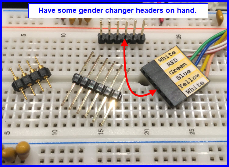
When making connectors like this, I always include a key pin so that it's impossible to connect them the wrong way round. For this one, I would use seven pins, snip off pin 2 and force it into the connector at position 2, which has no wire connected to it. I recently released the smoke in a 2.5" IDE hard drive by connecting it the wrong way round!
larryd:
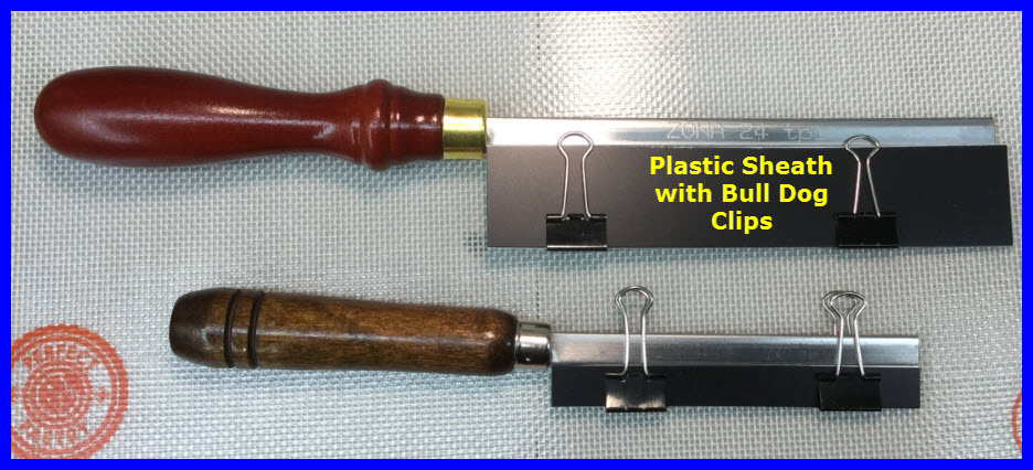
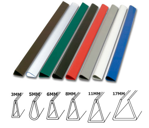
Easier and cheaper, to protect the teeth are these.
Binding strips
Easily cut to length by the saw itself and no clips needed.
Your local stationers probably sell them individually.
Good idea!
Henry_Best:
When making connectors like this, I always include a key pin so that it's impossible to connect them the wrong way round. For this one, I would use seven pins, snip off pin 2 and force it into the connector at position 2, which has no wire connected to it. I recently released the smoke in a 2.5" IDE hard drive by connecting it the wrong way round!
How is that printed label on the connector housing made ? (Post #444)
I printed it on a full page label using an ink jet printer.
I laminated it with clear packing tape then cut it to size.
See the ZIP file (WORD) and PDF attachments below.
MD5 for ZIP file is 8DFBED52BD713026C776B4490838C00C
Header label LEDandSwitch PCB X6.pdf (133 KB)
Header label LEDandSwitch PCB X6.zip (12.6 KB)
Arduino Pro Mini interface board. Plugs directly into the bus lines of the breadboard, and has both male and female headers along the side.
ESP-01 Programming board with integrated 3.3v regulator and easy access to the GPIO pins as well as a header for connecting an FTDI board. Not my best work, but it's functional, and it was about 20F in the workshop when I put it together.
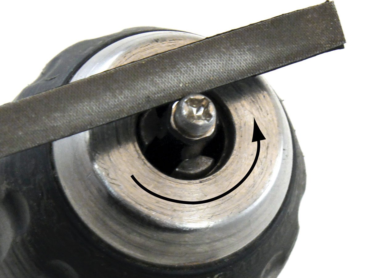
If you have a tight fitting head on the screw, you can cut it down with a file and a electric drill.

To protect the threads, thread the screw into a standoff.
1 Like
A few from my palette of neat tricks:
A pair of pliers with an elastic band around the handles makes a very convenient desk vice for soldering. CAreful of your fingers if it slips and they snap shut! I have the scars to prove this hurts ![]()
Blu tack or putty can be used to hold things in place while soldering, but can leave residue if the blutak gets hot.
Servo leads (JR/Futaba) make convenient 3 pin leads with already attached male or female header pins. They are cheap and available in large multi-packs.
A simple hardware store 20W/30W/50W 12V halogen spotlight bulb can be used to create a nice hefty load on a DC circuit.
You can use the built in LED of the arduino to flash error codes when you have no serial or screen attached. Blink the LED as a heart beat, on error, flash it much more rapidly. So 1 flash = success, n flashes = error code.
You can use the built in LED of the arduino to flash error codes when you have no serial or screen attached. Blink the LED as a heart beat, on error, flash it much more rapidly. So 1 flash = success, n flashes = error code.
Excellent idea!
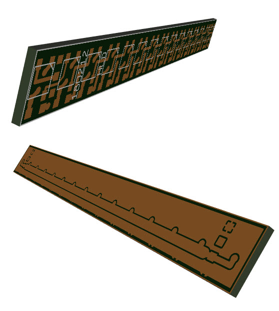
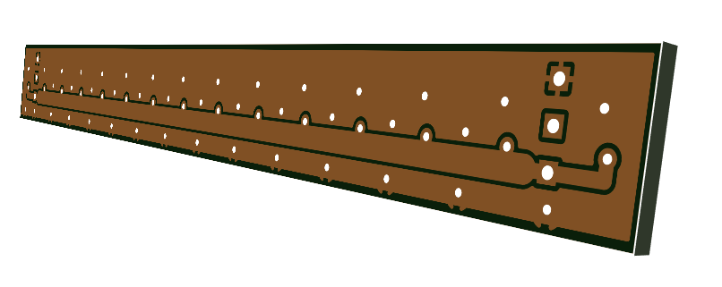
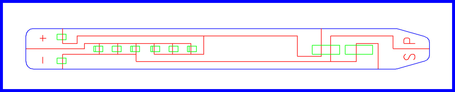
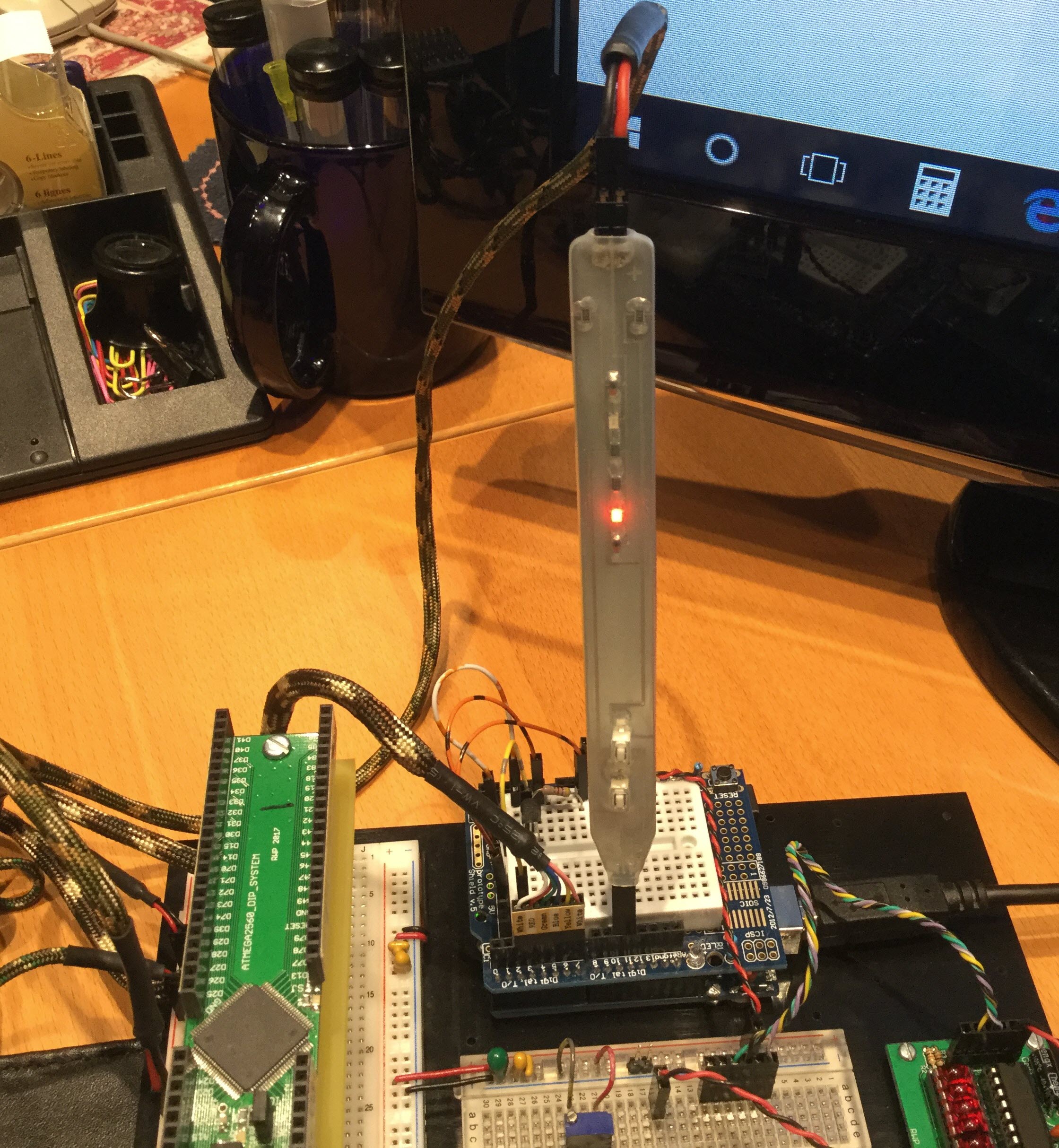
Make yourself a simple but very useful Logic Probe with Logic Pulser.
Resistors, diodes and LEDs are 1206.
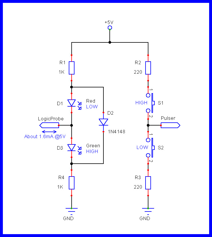

EDIT
- D2 has now been added.
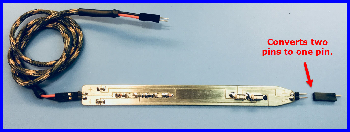
I find there are many times when I need to access an Arduino header pin with several external devices.
You can make a simple interface with male and female headers.
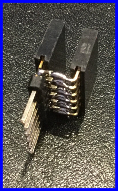
Cut a 6X1 male header and two 6X1 female headers.
Solder them as shown in the images below.
If you have a long pin (stackable) female header, you 'don't need the male' header. ![]()
Neat... ![]()
![]()
![]()
Got to get my inventory under control. ![]()
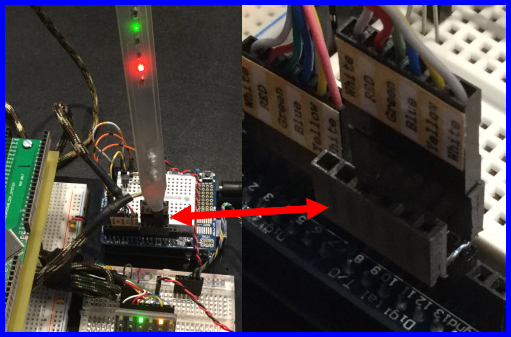
I did have some stackable female headers.
These turned out much better.

If you have access to a Logic Analyzer or a Storage Oscilloscope, you can use them to time events when troubleshooting your code.
A write to pin D13 on the Arduino using the PINB command, toggles that pin’s state.
Toggle: if the pin was ON it goes OFF, if it was OFF it goes ON.
examples:
PINB = 0x20 // Toggle D13 ATMEGA 328
PINB = 0x80 // Toggle D13 ATMEGA 1284 or the ATMEGA 2560
Having two of these commands in a row gives a pulse of ~62.5ns (nano seconds) for 16Mhz clocks.
Creating a pulse on D13 can be used to mark the being of some code.
Adding a second pulse on D13 at the end of that code times how long that code took to execute.
- The first image shows the timing relationship between the two PINB = 0x20; instructions, ~60ns.
- The second image shows how long it takes to go from the end of loop() back to the beginning ~1.13us and it shows the time it takes to go between the two pulses ~100us.


See also post #968
PCB price comparisons. <----<<<<
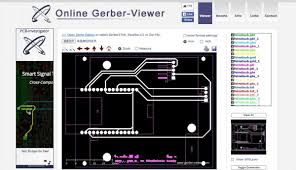
Online gerber viewers:
Upload your zip file
https://circuitpeople.com/ <----<<<<
Upload your zip file
http://www.gerber-viewer.com/default.aspx <----<<<<
Upload gerber files, one at a time (not zipped)
Wireless Data Acquisition and Data Logging Systems with Wireless Sensors - Paragon Robotics <----<<<<
EDIT
This site needs you to drag your non zipped file(s) onto the web page.
You then re-assign your files to equivalent surface names.
You can then orbit the 3D PCB rendering using your mouse.
webGerber <----<<<<