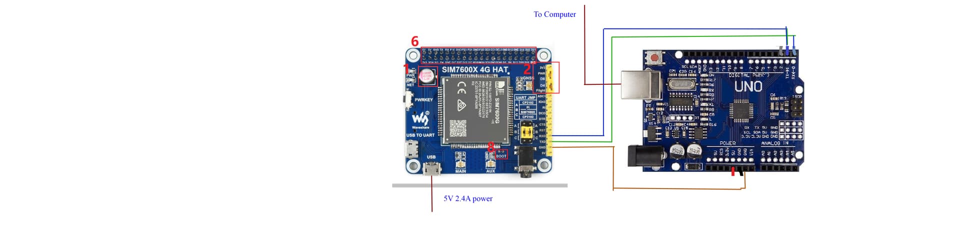
The Arduino is powered through the barrel jack by a 7.5v 2A power supply and is plugged into the computer through usb. I’ve also tried disconnecting the power link between the sim and their Arduino and powering the sim through its microusb and a 5v 2A power pack. But the same thing happens and the powerbank autoshuts off after awhile.
So I have two questions. What might the problem be and does anyone have a suggestion for a good power pack I can use to power the sim?
I am using the example code below
#include <Waveshare_SIM7600.h>
// Pin definition
int POWERKEY = 2;

char phone_number[] = "XXX";      //Store the phone number you want to call

void setup() {
  Serial.begin(9600);
  sim7600.PowerOn(POWERKEY);
  sim7600.PhoneCall(phone_number);
}

void loop() {

}
I trust you realise that the ground must always be directly connected between the two devices.
Now I really do not know about the SIM7600 but I would say you should be powering it with a proper 5 V via its "5V" pin and ground. If your "power bank" shuts down, it is telling you that whatever it is connected to, is not drawing significant power - for whatever reason (either it simply does not require much current, or is not connected properly).
The fake "UNO" (as you have pictured it that is not actually a UNO as it does not have a 16U2 interface chip) is something of a problem. You are not supposed to power it from the "5V" pin while it is connected to a PC by USB but if not connected to an actual PC, then regulated 5 V to the "5V" pin is the proper way.
A very useful and generally inexpensive power supply for Arduino systems a a USB "phone charger", generally rated at either 1 A or 2.1 A - or more.
The sim is connected to a power supply it still gives me the constant AT serial print. The sims power light is solid and the net light continues to flash rapidly.
Somewhat remarkable that it does that - I see no ground connection between the two now!
It is not at all obvious what you are trying to achieve. You appear to have the SIM connected to the same connections on the Arduino as are used by the serial monitor. What is it you expect to happen?
okay well I am used to using a sim shield which communicates just fine to the serial monitor through a connected arduino . so what way should I connect it then? All I want to do is to simply use the sim through the arduino.
Here is my revised connection which still doesn't work.
So this has nothing at all to do with the serial monitor then.
The point is, the Arduino has one serial port, connected to "pins" 0 and 1 as well as the USB interface. You can either have it "talking" to the GSM board or the serial monitor - not both.
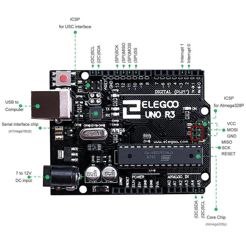
If you want to communicate with the GSM board, you generally must disable the USB interface on the UNO. If it is a real UNO, you do that by jumpering pins 5 and 6 on the ICSP header for the 16U2.
If it is not actually a UNO but a Duemilanove clone using a CH340 as your pictures indicate, then I do not know how you disable the USB interface. It may or may not matter depending on how the serial connections on the GSM board work.
It has the chip you are talking about. If I understand you correctly I jumper the two pins in the red box and then I can communicate with the chip with my latest wiring through the arduino's usb interface?
The thing I don't completely understand Is that I used the uno before with this shield
it doesn't touch the ICSP pins at all when it sits ontop the UNO and with this I was able to communicate just fine with the sim chip through the arduino's usb as far as I could tell.
Depends on what you mean by a "UNO". That one is a real UNO with a 16U2 interface chip. But a lot of what are sold as "UNO" are not UNOs at all, just versions of the earlier Duemilanove but using a CH340 or similar instead of the deprecated FT232.
The confusing point is that you have three things connected together at pins 0 and 1 of the UNO. You have the TX and Rx pins of the ATmega328, you have the RX and TX pins of the USB interface, and you have the TX and RX (or RX and TX) pins of your SIM7600.
The question is - what do you want to "talk" to what? If the SIM7600 were not connected, then the ATmega328 talks to USB. But with it connected you can either have the ATmega talk to your SIM7600 - which means you are not using the USB to talk to the serial monitor, or you can use the USB to talk to the SIM7600 and have the ATmega do nothing.
Which is it? If you want to disable the ATmega, you jumper pins 5 and 6 (not what you have shown at all) on the ICSP header next to that chip. If you want to disable the USB interface instead, you jumper pins 5 and 6 on the ICSP header next to the 16U2.
Does your sim7600A-H or 7600E-H work on USA bands? are you in the USA? i am trying to replace a 3g project with a 4g lte and had purchased 7600ce-t in error.
Please advise. appreciate any help!
Paul
No idea why you are connecting a 7.5 V power supply to the "barrel jack" on the UNO. It can only draw 200 mA at most anyway when powered by the "barrel jack".
You should connect the same 5 V supply as the sim7600 to the "5V" pin on the UNO except when connected to a PC by USB.
Don't know if you solved it, but an easy method to check communication was to use this script:
#include <SoftwareSerial.h>
SoftwareSerial myserial(2,3); //Define virtual serial port name as myseria,Rx is port 7, Tx is port 8
void setup()
{
  myserial.begin(115200); //Initialize virtual serial port
  Serial.begin(115200); //Initialize Arduino default serial port
}

void loop()
{
  while(1){
  while (myserial.available()) {
    Serial.write(myserial.read());//if Serial received data, output it via mySerial.
  }
  while(Serial.available()) {
    myserial.write(Serial.read());//if myserial received data, output it via Serial.
  }
}
}
After this go to serial monitor and try to send AT as Command to see the answer.
Then you can use Fona library to inspire you to write your code.