I'm wanting to get to grips with using a current loop as a way of sending a basic binary signal from one microcontroller to another. In light of this I have got the following circuit:
The simulated circuit can be found here. It appears to be working a treat in the simulator and don't see why it wouldn't when breadboarded. To be clear, the microcontrollers (Arduino Out, Arduino ADC) in the above circuit are two separate microcontrollers and separated by a distance of at least 100m.
A couple of questions though if I may:
Is there anything obvious that I'm missing here, or is it looking okay?
From what I've read current loops have excellent noise rejection and background electrical noise is not much of an issue. Why is this? Consider the above circuit, assume the data cable is placed with a mains cable. Why would the mains cable not induce a voltage within the data cable and mess up the readings?
Current loops work because you are monitoring current. Noise is voltage. Where current loops do NOT work is when you run the wires over florescent light fixtures containing ballast transformers. The induced current from them can also make the current in your loop add or go to zero every time the mains in the ballast reverses. I have see 20ma. current loops for computer terminals go crazy until the wires were moved.
Paul
A current loop was created to transmit analog data long distances. Current loops do not have excellent high frequency rejection as the current source is unable to "cancel" and spurious signals coupled into the loop. However the receiving end has relatively low impedance making it difficult for stray signals to couple in.
Your schematic:
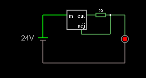
assuming your regulator is a version of the LM317 then the output is 1.2 volts across. This generates ~ 60 ma. 60 ma through 20 ohms is about 13volts. This will damage your Arduino input.
Your simulated circuit is interesting, however unfortunately you really need to understand the circuit to get realistic results. Its best to have a general expectation of what the circuit does before trying to simulate it.
However the receiving end has relatively low impedance making it difficult for stray signals to couple in.
Is there any reading for a beginner that you could recommend on this subject?
assuming your regulator is a version of the LM317 then the output is 1.2 volts across. This generates ~ 60 ma. 60 ma through 20 ohms is about 13volts. This will damage your Arduino input.
My apologies, I'm not following this at all. Take a very simple circuit such as this:
The LM317 is dropping ~ 21 volts and is outputting a constant current of ~22 ma and there is a voltage drop of ~ 1.8 volts across the LED.
60 ma through 20 ohms is about 13volts
Again my apologies, I'm not understanding this? 0.06 A x 20 Ohms = 1.2 volts.
How is this circuit of the LM317 so different from mine that my circuit would damage the microcontroller?
Its best to have a general expectation of what the circuit does before trying to simulate it.
To be honest I thought I had... Oh dear! On a side note, is this simulator really so bad?
The simulator won't tell you anything about how the current loop will behave in the real world.
Isn't that the whole point in simulating, that after working things out, it can then be simulated and then put into a physical test? If not, then why have a simulator at all?
It would quickly destroy an Arduino.
Thanks for that, but to be honest it's not much for me to go on... If you'd expand I'd appreciate it as to why.
Hi,
When you talk about current loops and noise, you should be talking about RS485.
A single current loop is used so that the loop can power the sensor and over come long wire lengths and hence relatively elevated resistance.
A loop system with 1 Ohm resistance will with a 4-20mA loop have say 10mA flowing through it, even if the loop resistance increases to 5 Ohms, still 10mA.
If the transistor is off, 24V is applied to the "Arduino ADC". Although I don't know what is meant by the two input connections shown on the schematic.
The current source driving the loop is actively trying to keep the current constant. Current will be the same all the way along the cable to a good approximation (especially at lower frequencies). Thus the current source can absorb a lot of the interference.
This does breakdown at higher frequencies since stray cable inductance and capacitance will be able permit more discrepancy in current to arise along the cable, and be faster than the current source circuit can react to.
For a current loop to work well the receiving end needs good voltage compliance (it needs to be able to swing in voltage freely). Thus is normal to opto-couple at the receiving end (the MIDI standard being a good example).
Your circuit seems not to use an opto coupler, and for some reason is using analog sensing at the receiver, yet is driven digitally at the transmitter.
Hi,
I think this is the BASIC CIRCUIT you could be looking for, as it is only a ON/OFF signal, a 20mA loop that is switched ON/OFF should do the trick.
An optocoupler isolates and makes the reading of the loop easier.
Feel free to change, nit pick, advise on components.
The 68R value for the constant current LM317, is close enough to the 62.5R that is the calculated value for 20mA.