Simple Door Lock Actuator project causing significant overheating

Before I begin, I just want to say that I have been trying to figure this out on my own for at least a week- so I am not bringing my question (stupid though it may turn out to be) to the forum without attempting some homework.

I just finished building a secret bookcase door and was looking for ways to "secretly" lock and unlock it. After some research, I found this drumkit project and then this door-lock project both using car door actuators, which seemed perfect for my needs. The idea is to use two actuators (one at the top and one at the bottom of the door) pushing and pulling tube locks like the one shown in the second video (presumably not much force needed). So I built a proof of concept, using: 1) an arduino uno R3; 2) an arduino motor shield Rev3; 3) one of these car door lock actuators; 4) an old +12v/1.5a DC wall wart I had lying around; and 5) a "button" I made out of a paperclip.

The shield is plugged into the uno (with the exception of the vin pin, which is bent out of the way). The wall wart positive wire is screwed into the shield's vin and the negative wire into the shield's gnd. The actuator's two wires are screwed into Channel A (it's my understanding the polarity doesn't matter in this case) of the shield. I then made a button out of a paperclip- one button wire is plugged into Pin 2 and the other into GND on the "digital" strip of the shield. I cobbled the code together from various sources (keep in mind that I'm relatively new to arduino programming), which is here: Arduino Actuator (test) - Pastebin.com. The idea is that one button push extends and a second push retracts.

However, when I plug in the wall wart, the motor shield (specifically the chip in the middle) immediately starts to get hot and is too hot to touch after about 10 seconds. This is without me doing anything with the actuator. On the plus side, the actuator/button combo works fine. Pushing the button fully extends and fully retracts the actuator.

But I am troubled that the shield would get so hot so quickly with just one actuator attached. I was hoping that I could leave the uno plugged in 24/7 with the idea that it would only be triggered two or three times a day, but am afraid to do this if the chip is going to be so hot at a "resting" state.

Any thoughts? Could it be my power supply? (see attached img file: "DC Power") My wiring? (see attached img file "Wiring"). My code?

I've seen folks on the forum bashing the Motor Shield because it is based on the L298, but I assumed that it wouldn't be a problem given how little I was asking it to do. I have no problem moving to a different setup (using relays or a different motor driver) if it gets me where I want to go, but obviously I'd prefer to get it working with the equipment I have (even if I had to add a part or two).

If the drum-kit guy is able to control so many actuators without an overheating problem (according to the comments in his Instructables thread), I can only assume the issue is on my end.

Would appreciate any thoughts,

eb

DC Power.jpg

Wiring.jpg

DC Power.jpg

Wiring.jpg

The door lock actuator likely draws 5 to 10 Amperes, much more current than a typical motor shield can deliver.

Use your multimeter to measure the winding resistance of the actuator and get back to us.
If you don't have a multimeter and intend to continue with the hobby, now is a good time to buy one!

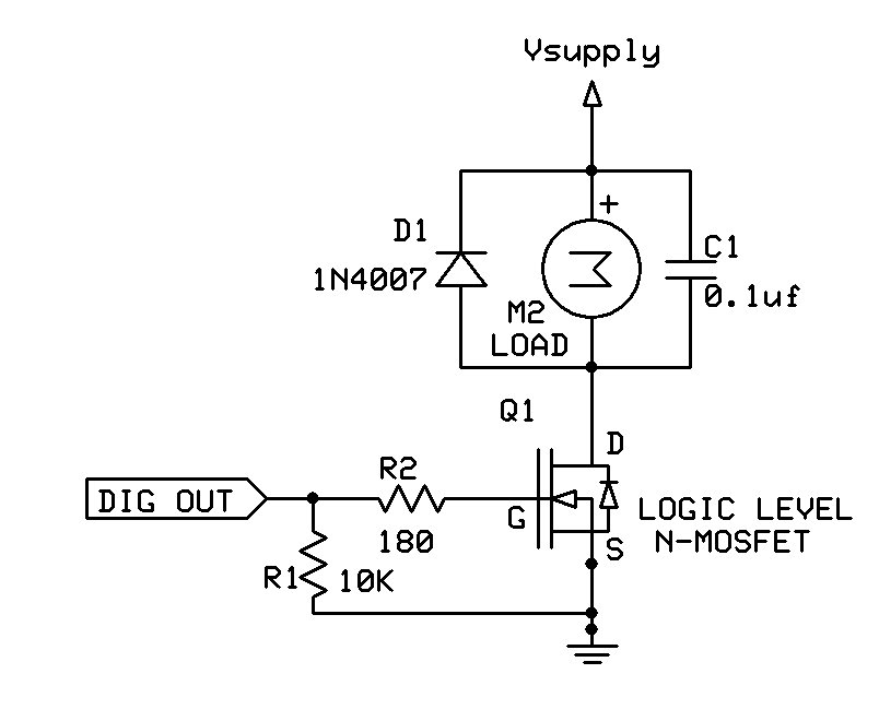
For something like an actuator, a simple MOSFET switch is cheaper and easier to use than a motor driver. Be sure to use a logic level MOSFET.

Typical circuit:

The other problem is the time you are applying power to the automobile door locks. Should not be for more than 1/4 second, or for however long it takes for the mechanism to move. Sounds like you are doing the movement and then continuing to apply power.

Paul

Thanks for the quick responses (and for sending me down a few more rabbit holes).

jremington:
I spent some time googling how to measure the winding resistance of a car door actuator and didn't find much guidance. However if I set my meter to test resistance and then touch a probe to the two wires coming out of the actuator (with no current), i get a result of about 3.3 ohms (regardless of which probe is touching which wire). Does that sound about right? Or do I have to actually open the actuator to get to the motor inside to properly test winding resistance?

With regard to using a logic level MOSFET, if that is the best solution, I'm happy to explore that route. However, is there one you can recommend based on my intended application (preferably able to handle enough power to drive two actuators at once)? There are a number of them listed here, but I'm having difficulty telling the difference between them.

Paul_KD7HB:
This is where I thought my problem might be. I thought the code I was using (Arduino Actuator (test) - Pastebin.com) only applied power for 100ms [delay(100)] before turning off, but maybe I'm not understanding the proper code to ensure that power is no longer being applied (or maybe 100ms is just too long).

Does flipping the brake channel to HIGH turn the motor off? Or just put on the brake while still sending power to the actuator? Essentially, I only want power to be applied to the actuator long enough to extend or retract and then for the power to turn completely off. There is not going to be any pressure on the actuator when the power is off so making sure the brake is actively engaged (e.g. powered) shouldnt be required, correct?

about 3.3 ohms

The actuator would draw about 4 Amperes from a car battery (13-14V).

The L298 driver can handle only 1 Ampere continuous current (2 A for a few milliseconds), and of course, your 12 V, 1.5 A power supply is woefully inadequate.

With a proper 12V, 5A (at least) power supply, you could try connecting the motor driver inputs and outputs in parallel. That should work to briefly pull in the actuator, for a fraction of a second.

Quote: "This is where I thought my problem might be. I thought the code I was using (Arduino Actuator (test) - Pastebin.com) only applied power for 100ms [delay(100)] before turning off, but maybe I'm not understanding the proper code to ensure that power is no longer being applied (or maybe 100ms is just too long).

Does flipping the brake channel to HIGH turn the motor off? Or just put on the brake while still sending power to the actuator? Essentially, I only want power to be applied to the actuator long enough to extend or retract and then for the power to turn completely off. There is not going to be any pressure on the actuator when the power is off so making sure the brake is actively engaged (e.g. powered) shouldnt be required, correct?".

The forum has a very nice capability to include your code in your post. Very few people will bother go go to another site.

You have the system there in front of you. measure the voltage on the actuator and see if it remains high. IF there is no mass being moved by the motor, there is nothing for braking to do. The motor stops immediately when power is removed. If you have questions about your setup, you can easily test them right there!

Paul

jremington:
For something like an actuator, a simple MOSFET switch is cheaper and easier to use than a motor driver. Be sure to use a logic level MOSFET.

The actuator would draw about 4 Amperes from a car battery (13-14V).

The MOSFET sounds like the way to go, particularly if I want to drive two actuators. Any chance you could recommend a specific MOSFET fitting these specifications? I have started to watch videos/read documentation on how to tell MOSFETs apart, as well as basic circut diagramming (I said I was new to this) and will continue to do so, but there are hundreds, if not thousands, of them out there and it's going to be a while before I fully understand how to read those datasheets (I was an english major, not an engineer).
Paul_KD7HB:
Again, thanks for the help. The initial post was my first post ever on this forum and I wasn't aware of the code posting etiquette. Doing my best to do my research before asking questions, but its a learning curve.

An N-channel logic level MOSFET like this one will be fine.

Look at the data sheet for drain current Id > 20 Amperes max, series resistance Rds(on) as low as possible at Vgs = 3V (e.g. less than 0.05 Ohm)

jremington:
An N-channel logic level MOSFET like this one will be fine.

Thanks. Ordered today. Also ordered a larger Power Supply. Thanks for the help!