Is that really the simplest form of this circuit I wonder?
They both use 10 gates, although the first one needs three 3input AND gates so I suppose the second circuit is a bit simpler.
I don't have any issue with that.,
So you don't think the decoder implemented by manucturer's is efficient?
I doubt you could improve it it much.
You need to control all 7 segments? You only seem to be decoding for 1 at the moment.
I can't comment on the efficiency of Texus Instruments ICs, I suspect they are quite good considering they've been doing it a while 8)
I need to build it using basic logic gates using the minimum number of gates and as that would get a bit busy for all 7 segments, I only need to get 1 element working.
I guess there is a clue in that Ti circuit diagram, but it's a bit tricky to follow.
Not really. Look at the LS49 diagram.
Each input becomes A, A/, B, B/, C, C/ and D, D/ using the inverter and the NAND gate.
Ignore the blanking input, and you can get by with the original signal and the inverter to make A, A/, etc.
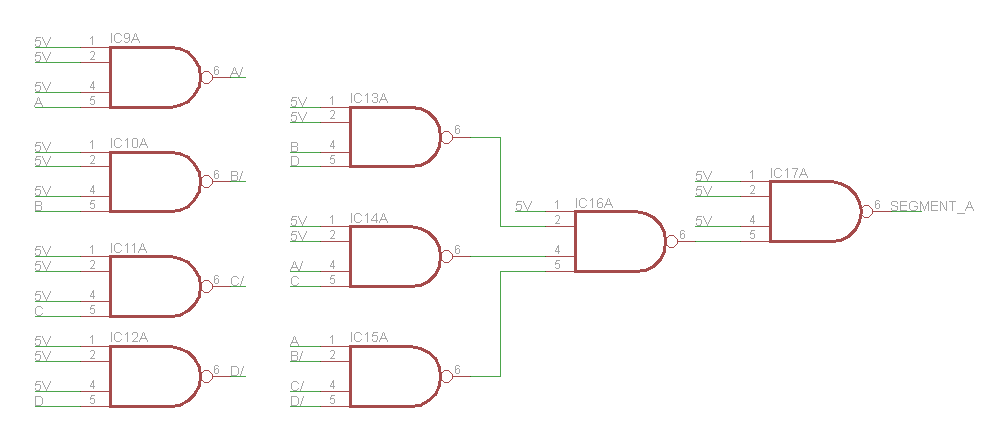
Then each output is just the 3 AND gates and the following gate to collect the AND gate outputs. If you make the AND gates all NAND gates, the final stage is just a 2 or 3 input AND gate.
So, A just becomes this:
And you could make the whole thing with 4 input NAND gates, tieing any unused inputs HIGH.