For my project I need to be able to determine the position (1 of 5) of a sliding switch.
I have wired a series of 1K ohm resistors between the switch position so that posn 1 would have 1K Ohms resistance, posn 2 would have 2K ohms, etc down to posn 5 with 5K ohms.
When I measure voltage with a meter I get 5 volts down to about 3.5 volts as I slide the switch from posn 1 to posn 5.
However when I try to read it using analogRead (pin A1) I get a pretty much steady 1023 (bounces a bit between 1020 and 1023) regardless which position the switch is in.
Clearly I'm doing something wrong.
Can anyone help?
Thanks!
Here's my code I'm using:
// include the library code: #include <LiquidCrystal.h> //used to display light values for testing
// initialize the library with the numbers of the interface pins
LiquidCrystal lcd(12, 11, 5, 4, 3, 2);
Dblackb99:
Yes, it has 5 discrete switch positions.
But I think the point is that the ends of the resistor snake have to be at 5V and GND, and you tap off the voltage at the various positions. Maybe this pic is better, with a normal pot for comparison.
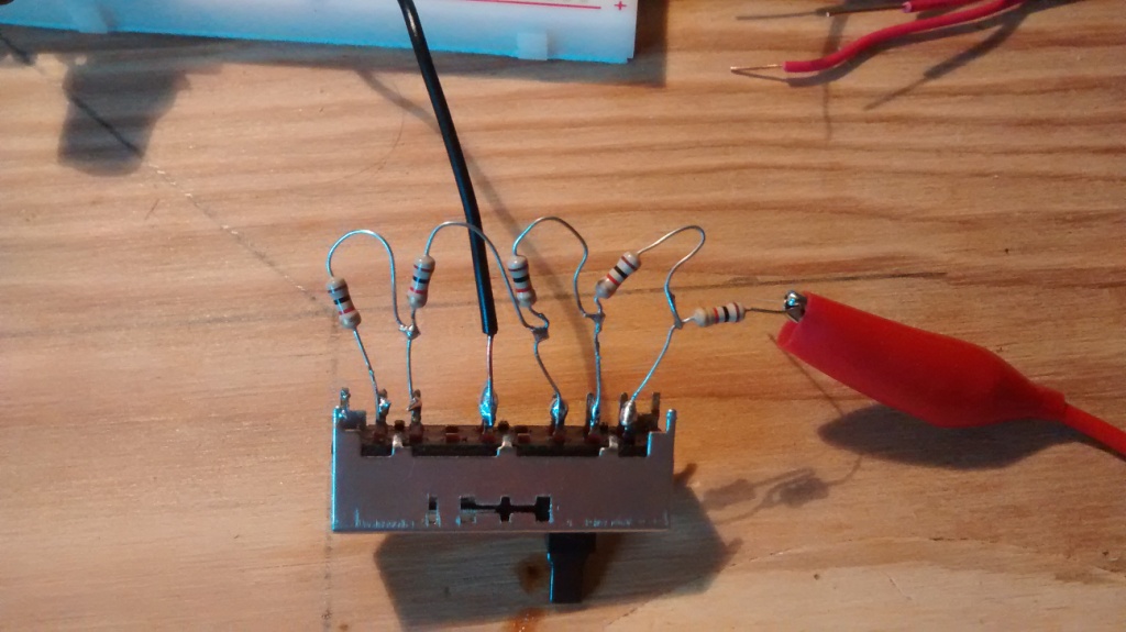
Yup, rookie mistake. Needed another resistor and connection to ground. Here's my latest setup and it's working fine. Just need to test for voltage on A1 and I can determine the switch position. Thanks everyone for your help!
Just for future benefit, could you sketch out the actual circuit inside that switch? Or link a data sheet and I'll try do one in Express if you like. .... or is it as I had in my previous post? (Might not have the right number of elements though.)
Also a good idea to go back to top post and add SOLVED to title.