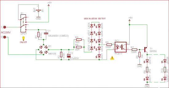
Hello, I have a circuit below from this website here and it is a backup led circuit for when the mains powers fails.
In this circuit the 230v mains supply is rectified and R2 and C2 are used to smooths out the Dc voltage and this voltage powers the combined forward voltage of the LEDs and before the end of the LED string, power is tapped to turn on the Photo-coupler which pulls the base of the PNP transistor high, thus keeping it off. When mains power is turned off the pnp transistor is pulled to ground through a resistor, thus turning it on and supplying current to the back-up LEDs.;
Is the way i explained it correct?
2)Is capacitor C1 (105 J/400v CBB22) used to step down the voltage, an alternative to
a
transformer?
3)What is the purpose of R3 and R4?
4)On the website it say switch1 (S1) is used as a power switch for the circuit but why is
9v need at the top of S1?
Thanks
Its capacitive reactance would step down the voltage to the bridge.
Current limiting.
‘Disconnects’ and saves the battery when you turn off the switch. The + terminal of the battery supplies the switch and hence the net name +9v.
Thanks for the reply larry
i dont understand 3 and 4.
3) doesnt the parallel path of the resisitors meet back together, so wouldnt the current
going out be slightly less than the lowest resistor, so the reason for the parallel path
and not the single equivalent resistance is for power dissaption purposes?
4) Why even have a DPST switch, what is the purpose of even having the second poll
that is connected to 9v and ground, i get that you want to be able to disconnect the
circuit but why not just have a SPST for the circuit?
doesnt the parallel path of the resisitors meet back together, so wouldnt the current
going out be slightly less than the lowest resistor, so the reason for the parallel path
and not the single equivalent resistance is for power dissaption purposes?
The two resistors are in parallel so the total resistance is 56/2 = 28 ohms.
We sometimes place resistors in parallel when we need a higher wattage resistor.
i.e. two 1/2 watt 56 ohm resistors gives us a 28 ohm 1 watt resistor.
These two resistors (28 ohms) limits the current to your LED string.
Why even have a DPST switch, what is the purpose of even having the second poll
that is connected to 9v and ground, i get that you want to be able to disconnect the
circuit but why not just have a SPST for the circuit?
Let's say you want to turn off the device completely.
You place the switch in the 'up' position, this removes the 250VAC from the first string of LEDs (1-9), they go out.
But, without the top part of the DPDT switch the battery would still be powering the second string of LEDs (right hand side).
This would kill the battery in time.
Normal conditions would of course be the switch is down.
larryd:
3) doesnt the parallel path of the resisitors meet back together, so wouldnt the current
going out be slightly less than the lowest resistor, so the reason for the parallel path
and not the single equivalent resistance is for power dissaption purposes?
The two resistors are in parallel so the total resistance is 56/2 = 28 ohms.
We sometimes place resistors in parallel when we need a higher wattage resistor.
i.e. two 1/2 watt 56 ohm resistors gives us a 28 ohm 1 watt resistor.
These two resistors (28 ohms) limits the current to your LED string.
Why even have a DPST switch, what is the purpose of even having the second poll
that is connected to 9v and ground, i get that you want to be able to disconnect the
circuit but why not just have a SPST for the circuit?
Let's say you want to turn off the device completely.
You place the switch in the 'up' position, this removes the 250VAC from the first string of LEDs (1-9), they go out.
But, without the top part of the DPDT switch the battery would still be powering the second string of LEDs (right hand side).
This would kill the battery in time.
Normal conditions would of course be the switch is down.
That makes sense, i didnt realize that the 9v in both sides of the circuit are the same battery.
Thanks again everything makes sense. I ,might try and build this circuit for practice. I just have to calculate for 120v mains instead.