So after one time again, common 1/4W resistors made my latest project much bulkier than it had to be, I finally gave SMD soldering a shot on the perfboard. I tried to find some info on the net, but didn't find as much as I expected, and if I found something (like this) people write stuff like "it's not ideal, but ...".
So, I tested it myself with 0603, and these are my first tries. Image, for some reason I cannot upload it because of "security concerns"
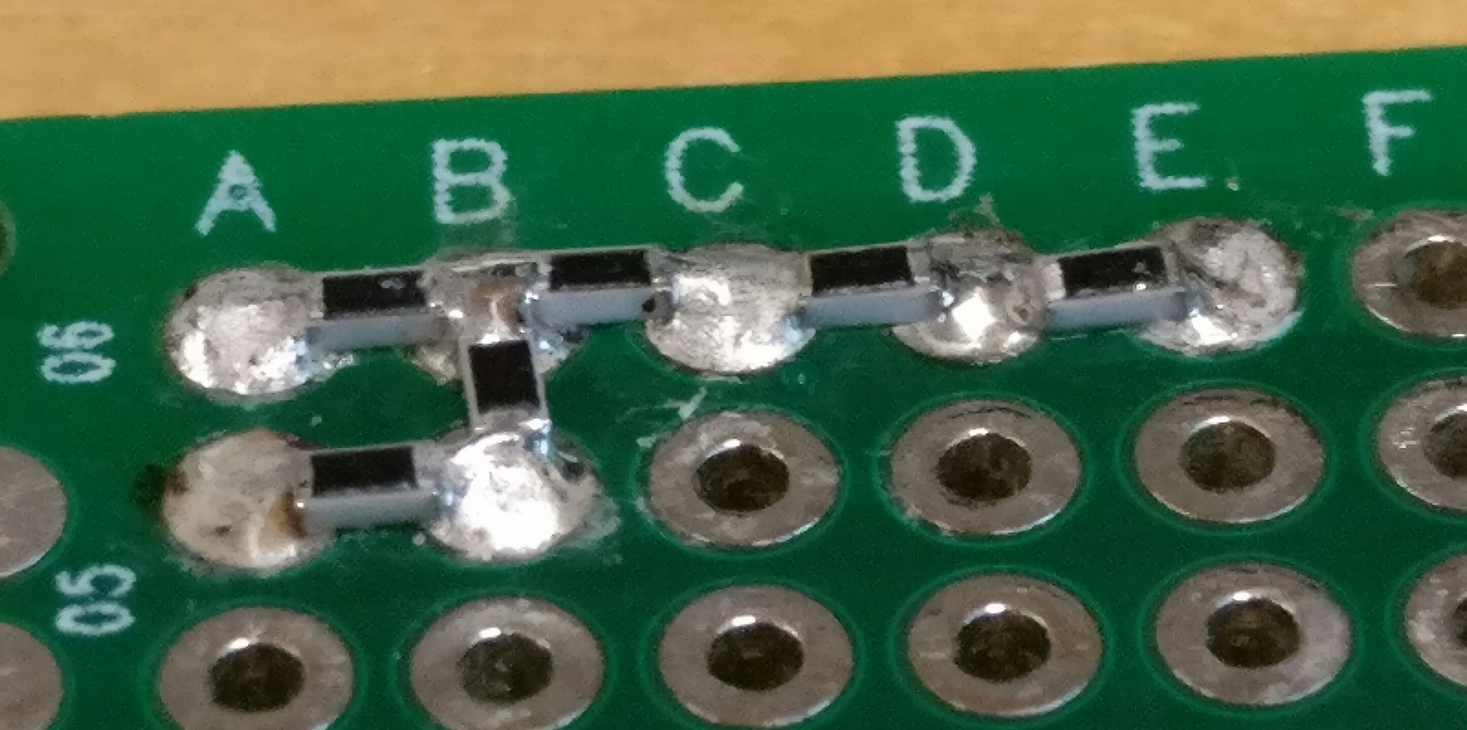
I mean, sure, they are not stunning, I experimented with different tips and solder sizes and not all were a good combination, but I think with just a little more practice, there is not a problem at all. Could already live with the left one, I guess. They all test totally fine and even the right ones look perfectly connected under the microscope.
Suddenly, a resistor that took 4 holes on the perfboard now fits between 2, the caps of an LDO fit directly under it instead of clogging up a good part of the rest of the board (especially when multiple are needed on each rail), mistakes are much easier to fix (never was very good with a solder sucker ...), parts are cheaper and easier to sort (my through-hole resistors in little plastic bags are a mess, while there are these cute little dirt-cheap interconnecting boxes for SMD) and all that goodness.
Why do I write that?
It's so awesome and at the same time apparently so comparably uncommon, that I am getting suspicious. Why isn't everyone doing that? Is there some hidden downside? Is it just much harder on perfboards that are not plated through, and those are still uncommon (though also dirt-cheap nowadays)?
And if nobody comes up with any substantial downside: Try it, it is much easier than I thought.
Finally, of course, I appreciate tips. Sticking it into a blob of solder like on the left seems easiest. It also makes it easier to add components in to other directions to that hole. On the right, there are tries to use fine and much less solder and get some kind of fillet on the component. Would there be a reason to go for that?
Hi,
I have had to do that at time to and it makes a nice small potential divider.
It looks as though you need a bit more heat, and or more time with the iron in contact with the joint.
Don't be worried at this stage about being in contact to long, you need to get the solder joint smooth.
It looks like you are trying to be quick and conservative, don't, these are cheap components, try higher temp, longer contact and see how far you can go.
Practice makes perfect and you have to break eggs etc etc etc
Good first try.. use the fine solder, are you using lead or leadfree solder?
Thanks. For this, I used Sn-3.0Ag-0.5Cu solder with 3.5% flux content, since I did this in the institute.
I used an Ersa solder station at 350°C. Perhaps I did not give it enough time.
Won't be at my solder station at home until the end of next week, but there, I will use lead solder, but on a cheaper solder station with a self-filed chisel tip.
You suggest to use fine solder, so you discourage to do it like I did on the left? I mentioned a few advantages I saw in that method, what are the disadvantages? I am not quite sure if not enough heat is the problem. I am more under the impression that the little solder I used on the right is sucked into the plated hole. That is probably energetically better than building a fillet on the side of the SMD components. This is one of the reasons I found just looking at SMD hand-soldering tutorials is not enough.
The color of the joints would certainly be a bad sign for lead solder, but I haven't really come around the lead free stuff yet. I feel that stuff always kind of looks like that. (Don't worry, it is not my main job to work at that soldering station ;)).
Hi,
The advantage of lead based solder is they always produce a shiny joint when done properly.
Fine flux filled solder is best because it it is easy to control the amount of solder used.
Like I said don't be scared to over do your technique, that will show you how far not to go.
I made up a level shifter recently using two BSS138 transistors (surface mount SOT-32) and 4 eighth watt resistors on a small piece of 0.1" single sided prototype board:
Wow. I clicked on the "latest post" link, only saw post #6 and thought "F*** you, it was just a test, it was my first time and it doesn't look that bad!". Then I saw the context
I don't have SOT-32 right now, so I didn't test that. But I also send my first SMD PCB to production, will get some soon and then test how that feels on the perf board. TO-92 or -220 have never bugged me that much spacewise, though. It was always the resistors (they look so small, but they are always JUST too big go over just one hole cleanly) or caps that go over more than one row. So with the 0603 passives, there is already a good deal done for me. Could be nice though to do "double-sided" stuff, where e.g. a buzzer is on the top side and the driving transistor is under it on the bottom.
PS: Added a few resistors, removed a little solder with a wig from one of the joints and cleaned the stuff and I am quite happy. Guess I will stay with that and only use through hole if I e.g. need the power rating. I am not sure about bigger SMD packages, they may have problematic length. 1206 will fit from pad to pad but it might be harder to directly add another one. With 0603, at least three can easily go to one pad. A forth one should work with the right tip. (If I wanted to do that, I would probably file a needle tip flat, and come from the top.)
I had to solder an SMD resistor across a couple surf board pins once.
The surf boards are those SMD to DIP package adapter boards where you solder the SMD part to the board and the fingers break out into a DIP pattern so you can use it like a DIP package after that.
There were 28 fingers for a 28 pin SMD IC package, and after the IC was soldered a resistor was soldered onto two fingers and it jumped over one finger. Seemed to work ok i guess. That was the only resistor required for that board so it would have been a pain to have to add another board just for one little tiny SMD resistor. The surf board was for a SOP28 package.
EDIT: Sorry it was an SMD capacitor not a resistor, but same idea.
ElCaron:
Wow. I clicked on the "latest post" link, only saw post #6 and thought "F*** you, it was just a test, it was my first time and it doesn't look that bad!". Then I saw the context
On this forum, you are unlikely ever to be a victim of someones sense of humour, since that does not exist here. Sarcasm yes. Sense of humour no. Anyway, keep up those legendary soldering skills.
6v6gt:
Anyway, keep up those legendary soldering skills.
I'm confused, was that sarcasm again?
As I said, I found it so easy that I was suspicious why not everybody is doing it. I am definitely not fishing for compliments. On the contrary, I expected some amount of critics. I mean, people are even criticizing Dave Jones for his soldering, and that guy certainly has more experience than the perhaps 20-30 PCBs I ever soldered in my life.
Seriously, I think it is really easy for anyone who can halfway handle an iron. With the top left ones, I literally just melted a drop of solder on the pad and stuck the resistor in. Then, the other side is easy, because the component is fixed. For the ones on the right, I held the resistor with tweezers and transferred the first batch of solder on the iron. Some flux pen use could perhaps made that easier, but the only challenge is to not heavily shake with the tweezers, which are set down on the board. The iron is even a little stabilized by the hole. You could almost say, through-hole is more difficult because some components tend to fall from the back of the board (I always have that problem with screw terminals - see, that is where my solder skills are at ;))
If anybody tried this before and found it hard, the plated perf board might be the significant difference. Maybe the plated holes act as a solder buffer so it is more forgiving about the amount of solder.
Want to here something scary? I found a hole bunch of 0201 resistors, and I fear someone might be hand soldering them here. (A reflow oven is nowhere to be seen.) I wasn't even able to put them under the microscope because they flipped away from the tweezers. But we are a neuroscience institute, so there are people who are used to work on some seriously small scale.
Certainly done it on stripboard - but then I only use stripboard or tripad, not isolated pads.
Handiest for ceramic decoupling caps in my uses - for lots of the same resistor I just use a
through-hole resistor network since thats just like another chip and not as fiddly as SMD...
Nothing is new under the sun, anyone who is into electronics has done this kind of stuff many many times.
When making a one of project you do this kind of thing.
Since PCBs are inexpensive today, making several of the same thing with point to point soldering is seldom done.
Many components are now only available in a SMD form factor.
However, breakout boards are now offered and contain many hard to solder SMD devices.
Patching these boards together onto a mother board allows the tinkerer to effectively use complicated circuitry in the designs.
Nothing is new under the sun, anyone who is into electronics has done this kind of stuff many many times.
When making a one of project you do this kind of thing.
Of course I do not claim I have invented soldering SMDs to perf boards. The question was, of course "Why isn't anyone doing it all the time", and why aren't there a lot of tutorials, suggestions and "pro tips" about that around, despite the fact that I find it enormously handy compared to through-hole. That is what I was wondering about in my initial post, apart from the request for tips what is the best way (stick into blobs, go for little solder and fillets ...), which nobody really answered yet.
Since PCBs are inexpensive today, making several of the same thing with point to point soldering is seldom done.
I know, one of mine is somewhere between China and Europe right now.
Whenever you add solder to your iron tip then apply that solder ball to a component, the component should first have a small amount of flux on it prior to applying the solder ball.
When you touch your iron tip to a component, insert the solder (with flux core) at the point of contact between the iron and the component.
Use a hot iron ~410C.
Remove iron from the work when you see solder wetting.
IMO use 63/37 lead solder
BTW
There are lots of soldering videos on YouTube including ones for hand soldering SMDs.
Some older ones from 'Pace Inc' are very good
.
I am not sure how I could express myself clearer. I am not looking for a general guide how to solder, I know there are SMD soldering videos and have watched multiple. I have even mentioned using extra flux when transferring solder with the tip.
I'm specifically about the combination perf board and SMD. I see very few videos about that, it is rarely mentioned, and if found it mentioned people kind of treat it as an almost sketchy solution for special cases.
I started this thread to
find out if there any hidden trap (I cannot even imagine an example what that could be, though),
ask for recommendations specific to this usecase, especially the blob-vs-fillet question,
and finally, if there is no catch, recommend to other amateurs like me to give it a try, because I found it surprisingly easy.
This is getting ridiculous. One side give a little bit too much praise, the other tells me which way round to hold a soldering iron. This is getting nowhere.