Solar tracker based on 4 LDR (resolved)

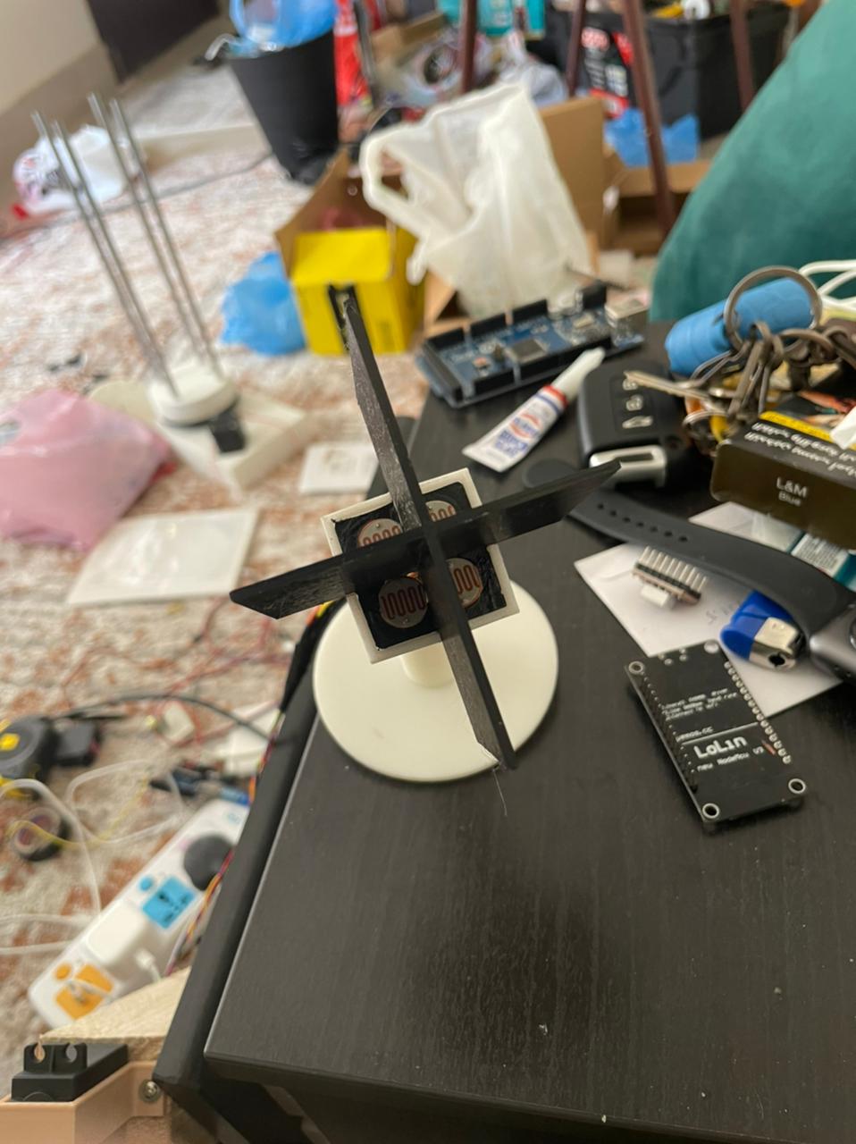
Hello everyone, I am working on a solar tracker project and I used four LDR sensors to detect the direction of the sunlight. since the set up is very big, I connect the four LDRs sensors with their resistors 10K to wires around 3 meters long to the Arduino Uno board.

The problem is that only the LDR connected to A0 pin show logical results of reading, every time I sweep between the wires on the analog pins, only A0 read correctly. :confused: :confused: :confused:

Here is the code - notice is not complete for the whole project - yet I need to check the reading of LDRs first.

#include <Servo.h>                   // include Servo library 
#include <AccelStepper.h>            // inlcude stepper library 


int actuator1 = 15;            //int = integer , float = 
int actuator2 = 16;
int actuator3 = 17;
int actuator4 = 18; 


Servo servo_SolarTracker; //  servo to move the solar tracker 
int servo_angle = 0;   // start at 0 degree     
int servoLimitHigh = 180;
int servoLimitLow = 0;

AccelStepper stepper1(1, 2, 5);        //pin 2 for controling steps and 5 for direction of stepper 1
AccelStepper stepper2(1, 3, 6);        //pin 3 for controlling steps and 6 for direction of stepper 2


void setup()
{
  Serial.begin(9600);    //only for testing 

  pinMode(actuator1,OUTPUT);
  pinMode(actuator2,OUTPUT);
  pinMode(actuator3,OUTPUT);
  pinMode(actuator4,OUTPUT);
  
  servo_SolarTracker.attach(9);   //attach servo signal to pin 9 in Arduino 
  servo_SolarTracker.write(0);    // move servo to 0 degree at first 
  delay(3000);        // wait for 3 seconds 

  stepper1.setMaxSpeed(100);   // set max speed of stepper1 motors
  stepper2.setMaxSpeed(100);   // set max speed of stepper2 motors 
}

void loop() 
{
  int tol = 35;       //tolerance 
  
  int lt = analogRead(A0); // top left
  int rt = analogRead(A1); // top right
  int ld = analogRead(A2); // down left
  int rd = analogRead(A3); // down rigt
  
  Serial.println(lt);        //only for testing 
  Serial.println(rt);
  Serial.println(ld);
  Serial.println(rd);
 
  
  int av_sunrise = (lt + ld) / 2; // average value sunrise
  int avr_sunset = (rt + rd) / 2; // average value sunset

  int diff = av_sunrise - avr_sunset;// check the diffirence of left and rigt
  
  
  //Serial.print(av_top);        //only for testing 
  //Serial.print(av_down);
  //Serial.print(av_sunrise);
  //Serial.print(avr_sunset);
  //Serial.print(diff);


  if (diff > tol) // check if the diffirence is in the tolerance else change vertical angle
  {
    servo_angle = ++servo_angle;
     if (servo_angle > servoLimitHigh) 
     { 
      servo_angle = servoLimitHigh;
     }
  
  servo_SolarTracker.write(servo_angle);
  }
  
 delay(500);
}

Try the usual trick of reading each analog pin twice. There's a tendency for each value to be impacted by the previous one you got.

I tried using LDR's for a solar tracker. The inherent hysteresis is to big for accurate tracking. I used photodiodes. Work great lasts a long time.

I wired the photodiodes cathode to 3.3V anode to 1M resistor, resistor to ground. A:D tap point at the photodiode/resistor junction.

Hi,
As @wildbill has said, read each analog input twice.

int lt = analogRead(A0); // top left
lt = analogRead(A0); // top left
 int rt = analogRead(A1); // top right
 rt = analogRead(A1); // top right
 int ld = analogRead(A2); // down left
 ld = analogRead(A2); // down left
 int rd = analogRead(A3); // down right
 rd = analogRead(A3); // down right

As there is only one ADC its input is multiplexed between the inputs you use, the ADC has a capacitor bypassing its input and it takes time for the voltage of the next pin being read to stabilise at the ADC.

By reading the same pin twice you allow the ADC to correctly convert the pin voltage value.

Tom... :slight_smile:
PS, Do you have dividing shades between your LDRs, so the sun casts a shadow if the platform is not aligned?

Thanks Tom and Wildbill, yes it works now. and of course, I designed 3D printed shade divider.

@Idahowalker , It is a project for a university course to show the idea of solar tracker, so the accuracy of LDR is too enough.

Hi,
Good to hear. Thanks for the reply.
As the originator of this thread you can edit the subject, it would be helpful if you added (Solved) to the subject.

Can you post a picture(s) of the LDR array so anybody interested can see how your hardware is assembled?

Thanks.. Tom.. :slight_smile:

My pleasure, here are the pictures attached. :slight_smile:

Hi,
Looks good, next the servos.
Tom... :slight_smile:

The project based on using two mirrors to reflect the sunlight perpendicular to the solar panel, so I used servo motor for moving the LDR arrays and two stepper motors to move the mirrors.

I put the photodiodes at the ends of the solar cells. The photo detectors are mounted so that the bottom surface of the solar cell is level to the face of the photodiode.

WARINIG!

    servo_angle = ++servo_angle;

THIS STATEMENT PRODUCES UNDEFINED RESULTS! It may do what you intended on some compilers but it will not do what you intended on all compilers or on the same compiler after an update.

Use one of these valid statements:

    servo_angle = servo_angle + 1;
    servo_angle += 1;
    servo_angle++;
    ++servo_angle;

This topic was automatically closed 120 days after the last reply. New replies are no longer allowed.