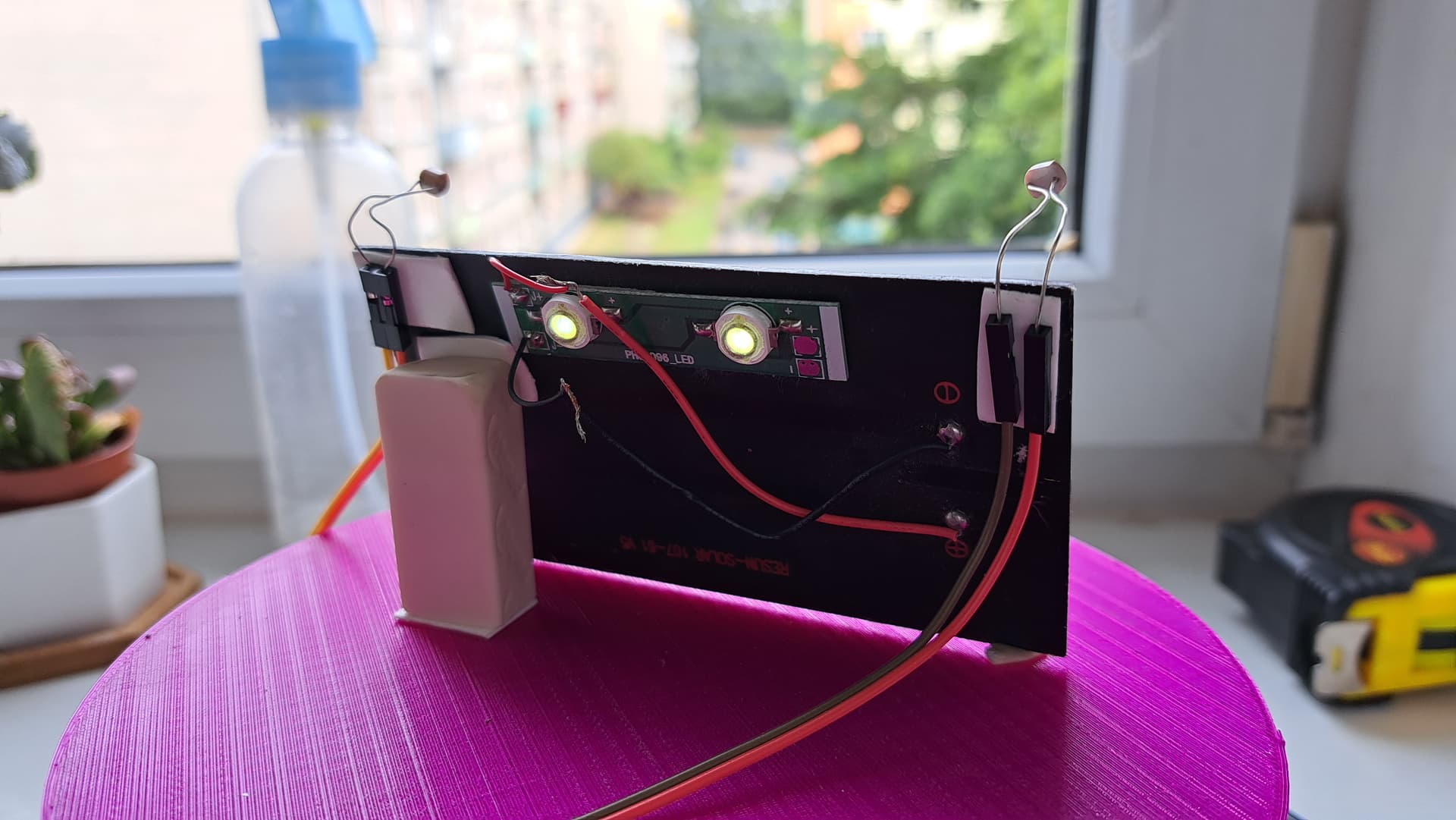
Trying to tinker with a solar panel + 2 photoresistors on the sides.
The idea is for two photoresistors to get the readings and rotate to the side which has higher value.
The issue I observe is, that when there is a stepper motor, the analog readings of the photoresistors are rather low (in Serial Monitor those are 17 and 19), as opposed to 700-800 when I don't have the stepper motor and if condition in the code.
// Include the Stepper library:
#include <Stepper.h>

// Define number of steps per revolution:
const int stepsPerRevolution = 160;    // Change to your specific stepper motor count per revolution

// Initialize the stepper library on pins 8 through 11:
Stepper myStepper = Stepper(stepsPerRevolution, 8, 9, 10, 11);

#define LDRpinL A0
#define LDRpinR A1

int LDRValueL = 0;
int LDRValueR = 0;

void setup() {
  // Set the motor speed (RPMs):
  myStepper.setSpeed(60); // Change to your specific stepper motor count per revolution
  Serial.begin(9600);
}

void loop() {
  LDRValueL = analogRead(LDRpinL);
  Serial.println(LDRValueL);

  LDRValueR = analogRead(LDRpinR);
  Serial.println(LDRValueR);


if (LDRValueL > LDRValueR) {
      myStepper.step(20);           // put - if opposite direction
      delay(50);
    }

  else if (LDRValueL < LDRValueR) {     // remove - if opposite direction
      myStepper.step(-20);
      delay(50);
    }

  else {
    // we want a case with do nothing

  }
Arduino Uno R3 (original, but not from Italy)
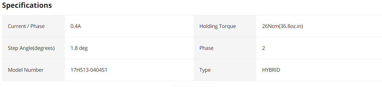
Stepper motor Nema17
Driver - L298D
PSU - 12V 1A adapter
You need to have your LDRs together side by side and a divider between them, this will cast a shadow over either of the LDRs when they are out of alignment.
Can you please post a circuit diagram?
Hand drawn and photographed is perfectly acceptable.
Please include ALL hardware, power supplies, component names and pin labels.
Circuit diagram. Software I used is called Fritzing. The circuit diagram has 220 Ohm resistor, but in reality it is 100 Ohms. There was no 100 Ohm element. Quick search gave me other nominal resistance resistors. So I used whatever closest was there.
Also, I use 12V 1A for power, but Fritzing has no such element. So, I just placed a 9V battery.
That's interesting idea. Never thought of that. Using RTC module. That would require adjusting for local time and having a wireless module if there are daylight changes.