I want to solder female header pins and IC header on my board, but this board is double sided, so how to solder properly to get connections between top traces and header pins? Maybe, someone know tutorial in Youtube and would like to share link?
Does your board have "plated thru holes"?
If not, leave a gap under the header large enough for a small tip. Solder the bottoms first, then reflow the top.
Or perhaps put in these Pin Receptacles, solder the header to them. http://www.dipmicro.com/store/index.php?act=viewCat&catId=474
It has some thru-holes. I was thinking of making more, but it would make my board much more complicated. If I would use reflow soldering, wouldn't plastic melt?
If it is a home made board making the Vias plated through hole is not worth the effort because you can simply solder a wire on both sides through the hole. Where you need them is under components you can not get to on both sides, like headers.
As a point of interest how are you plating through the holes?
Plated-through holes are not trivial to make, as it involves depositing a conducting layer
onto bare FR4 in the holes and then plating. If you solder a wire via then you don't have
a hole any more.
You can get surface mount female headers I believe, they may be easier to work with.
If you want the headers to sit flat, then add via next to each pin so you can connect top & bottom traces to allow the header pins on the bottom to connect to a trace on top.
As I said I don't want this method because it will make my board more complicated, there should be easier method. In example Arduino has headers which are soldered in both sides.
If you want the headers to sit flat, then add via next to each pin so you can connect top & bottom traces to allow the header pins on the bottom to connect to a trace on top.
Good idea, that means you have to plan ahead. . .
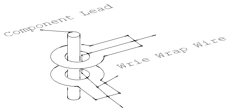
I sometimes use stripped wire wrap wire (30 AWG) with holes that cannot be easily accessed. I solder the wire to the top and bottom traces away form the pads, then add the component (ex: relays) and solder the bottom pad completely. This way the bottom pad is connected to the top trace by way of the wire wrap wire. (hope that makes sense)
I think Mark's idea bears repeating: Surface mount headers have pins the are L-shaped, and branch out to either side of the header, where they can be soldered to accessible pads on the same surface. The downside of this, of course, is that now all your traces have to be on the top side -- else you're back to vias again.