Hi all on this board.
I have been using the arduino for some time but have just started with the esp32.
I am having a problem loading a sketch with arduino IDE
Having tried many different settings and google searches I still cant get it to load....
I tried pushing the 'boot' button to start loading
I have added a 10uf capacitor between EN pin and gnd
I have tried 40mhz and 80mhz flash freq
I have tried different upload speeds
But still it will not load......
I can get it to send back info to the pc, using the serial monitor at 115200 baud I get >>
ets Jun 8 2016 00:22:57
rst:0x1 (POWERON_RESET),boot:0x13 (SPI_FAST_FLASH_BOOT)
configsip: 0, SPIWP:0x00
clk_drv:0x00,q_drv:0x00,d_drv:0x00,cs0_drv:0x00,hd_drv:0x00,wp_drv:0x00
mode:DIO, clock div:2
load:0x3fff0008,len:8
load:0x3fff0010,len:3480
load:0x40078000,len:7804
ho 0 tail 12 room 4
load:0x40080000,len:252
entry 0x40080034
.[0;32mI (46) boot: ESP-IDF v2.0-3-gbef9896 2nd stage bootloader.[0m
.[0;32mI (46) boot: compile time 05:59:45.[0m
.[0;32mI (46) boot: Enabling RNG early entropy source....[0m
.[0;32mI (65) boot: SPI Speed : 40MHz.[0m
.[0;32mI (77) boot: SPI Mode : DIO.[0m
.[0;32mI (90) boot: SPI Flash Size : 4MB.[0m
.[0;32mI (102) boot: Partition Table:.[0m
.[0;32mI (114) boot: ## Label Usage Type ST Offset Length.[0m
.[0;32mI (136) boot: 0 phy_init RF data 01 01 0000f000 00001000.[0m
.[0;32mI (159) boot: 1 otadata OTA data 01 00 00010000 00002000.[0m
.[0;32mI (183) boot: 2 nvs WiFi data 01 02 00012000 0000e000.[0m
.[0;32mI (206) boot: 3 at_customize unknown 40 00 00020000 000e0000.[0m
.[0;32mI (229) boot: 4 ota_0 OTA app 00 10 00100000 00180000.[0m
.[0;32mI (252) boot: 5 ota_1 OTA app 00 11 00280000 00180000.[0m
.[0;32mI (276) boot: End of partition table.[0m
.[0;32mI (289) boot: Disabling RNG early entropy source....[0m
.[0;32mI (306) boot: Loading app partition at offset 00100000.[0m
.[0;32mI (1481) boot: segment 0: paddr=0x00100018 vaddr=0x00000000 size=0x0ffe8 ( 65512) .[0m
.[0;32mI (1482) boot: segment 1: paddr=0x00110008 vaddr=0x3f400010 size=0x1c5f0 (116208) map.[0m
.[0;32mI (1499) boot: segment 2: paddr=0x0012c600 vaddr=0x3ffb0000 size=0x0215c ( 8540) load.[0m
.[0;32mI (1529) boot: segment 3: paddr=0x0012e764 vaddr=0x40080000 size=0x00400 ( 1024) load.[0m
.[0;32mI (1552) boot: segment 4: paddr=0x0012eb6c vaddr=0x40080400 size=0x1b028 (110632) load.[0m
.[0;32mI (1631) boot: segment 5: paddr=0x00149b9c vaddr=0x400c0000 size=0x00034 ( 52) load.[0m
.[0;32mI (1632) boot: segment 6: paddr=0x00149bd8 vaddr=0x00000000 size=0x06430 ( 25648) .[0m
.[0;32mI (1648) boot: segment 7: paddr=0x00150010 vaddr=0x400d0018 size=0x7a56c (501100) map.[0m
.[0;32mI (1676) heap_alloc_caps: Initializing. RAM available for dynamic allocation:.[0m
.[0;32mI (1698) heap_alloc_caps: At 3FFBA6B8 len 00025948 (150 KiB): DRAM.[0m
.[0;32mI (1719) heap_alloc_caps: At 3FFE8000 len 00018000 (96 KiB): D/IRAM.[0m
.[0;32mI (1741) heap_alloc_caps: At 4009B428 len 00004BD8 (18 KiB): IRAM.[0m
.[0;32mI (1762) cpu_start: Pro cpu up..[0m
.[0;32mI (1773) cpu_start: Single core mode.[0m
.[0;32mI (1786) cpu_start: Pro cpu start user code.[0m
.[0;32mI (1847) cpu_start: Starting scheduler on PRO CPU..[0m
.[0;32mI (1909) uart: queue free spaces: 10.[0m
Bin version:0.10.0I (1911) wifi: wifi firmware version: c604573
I (1911) wifi: config NVS flash: enabled
I (1914) wifi: config nano formating: disabled
I (1922) wifi: Init dynamic tx buffer num: 32
I (1922) wifi: wifi driver task: 3ffc4f34, prio:23, stack:3584
I (1928) wifi: Init static rx buffer num: 10
I (1932) wifi: Init dynamic rx buffer num: 0
I (1936) wifi: Init rx ampdu len mblock:7
I (1939) wifi: Init lldesc rx ampdu entry mblock:4
I (1944) wifi: wifi power manager task: 0x3ffca2dc prio: 21 stack: 2560
I (1950) wifi: wifi timer task: 3ffcb35c, prio:22, stack:3584
.[0;31mE (1956) phy_init: PHY data partition validated.[0m
.[0;32mI (1986) phy: phy_version: 329, Feb 22 2017, 15:58:07, 0, 0.[0m
I (1986) wifi: mode : softAP (9c:9c:1f:c9:64:15)
I (1989) wifi: mode : sta (9c:9c:1f:c9:64:14) + softAP (9c:9c:1f:c9:64:15)
I (1993) wifi: mode : softAP (9c:9c:1f:c9:64:15)
My setup is>
Windows 10 pro pc
Arduino IDE ver 1.8.14
esp32 devkit v1
If anyone can help it would be great.
Thanks
David
You have to push and hold the Boot button until you see "Connecting....." in the terminal window. Then release the button and it should load.
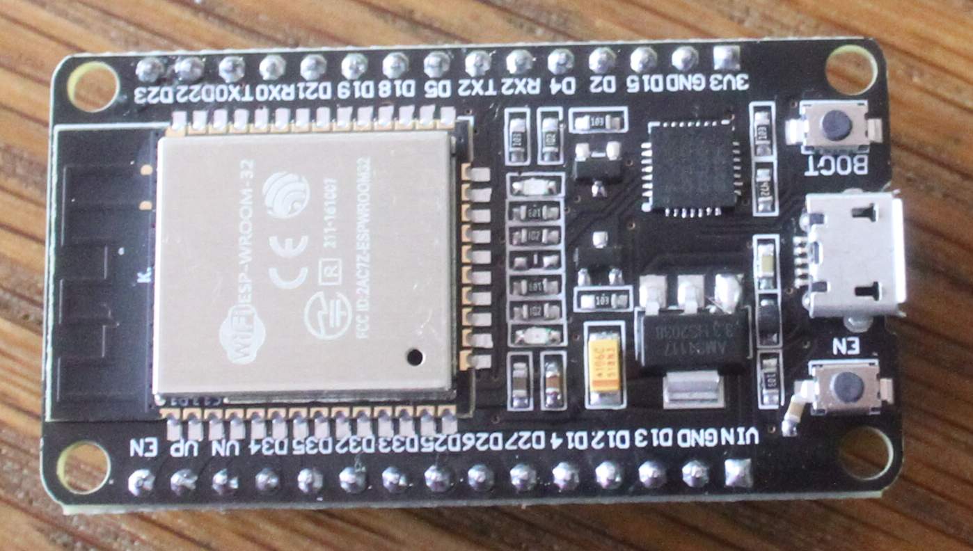
Can you post a picture of your ESP32-board?
to state the obvious: did you install the ESP32-board through the board-URL in the preferences? and then used the board-manager to install ?
Can you post the output of the arduino-IDE if you start the upload?
best regards Stefan
Thanks for the replys..
Ok I have tried pressing the boot button until "Connecting....."
I have also tried keeping it pressed
(the boot button is working ok I tested it with a multimeter)
Its installed in preferences using
https://dl.espressif.com/dl/package_esp32_index.json
And I have selected Board:'DOIT ESP32 DEVKIT V1' in the tools menu
I have the correct com port selected (com 5)
windows device manager identifies it as 'Silicon Labs CP210x USB to UART Bridge (COM5)'
Upload output from IDE is>
esptool.py v3.0-dev
Serial port COM5
Connecting............................_____....._____An error occurred while uploading the sketch
_
A fatal error occurred: Failed to connect to ESP32:Timed out waiting for packet header
Thanks again for all the replys....
Did you do the tests with nothing connected to the ESP32 or was something connected. There are two IO-pins that need to be in a certain state to enter flash-mode.
I don't remember the exact sequence when to press the button. But I do remember that I had a ESP32-board where I had to press the EN-button instead of the boot-button to make a reset.
Which means the buttons were labeled the wrong way.
So I would do testing all variants:
start upload until Arduino-IDE prints connecting ..... then press EN-button
start upload until Arduino-IDE prints connecting ..... then press BOOT-button
start upload press EN-button before Arduino-IDE prints connecting .....
start upload press BOOT-button before Arduino-IDE prints connecting .....
press button short (half a second)
keep button pressed for several seconds
You wrote that you had connected a 10 µF capacitor (10 mikro-Farrad between enable-pin and ground.
I used 10 nF-capacitors (nano-Farrad)
As an additional question: Did you buy this ESP32-board from a company named JOY-IT ?
best regards Stefan
Hi,
What you have got now in post #5 is what you get when the ESP32 is ready to get the upload.
Pressing BOOT should get it to begin the upload.
Is this you actual controller.
Where is the 10uF capacitor?
I have used 10uF with 100% success .
It should be a polarized capacitor, did you connect it the correct way around?
Tom... 


This seems to be the most common ESP32 problem. there are so many "just do this" techniques that obviously none of them work, if one worked everyone would tell you to use that one technique.
I am wasting my time on a TTGO OLED LoRa SD card equipped ESP32.
that which is called the boot button shorts GPIO0 to ground. no boot button on this device.
that which is called EN or ENable is the reset button. pressing this shorts RST / EN to ground.
in theory, you press the BOOT button, then terminate the program by pressing the reset button, then release both. this does terminate the preloaded demo program, but...
if you connect via ttyUSB0, you get a very long error message for your trouble.
if you connect via ttyAMAO, you get the Connecting....____ for too long, then the packet header error message.
every conceivable combination of shorting to BOOT and EN to ground, through a 2.2k or 3.3k or 10k resistor,
with a 10uf and a 100uf capacitor from RST to ground, with and without a 2.2 k resistor in line,
powered by the USB cable, or with external 5VDC to the 5V pin, has been tried. no effect, ever
you may think, try the ESP IDF. the instructions tell you how to install it, but not how to start it.
I have tried all combinations of pressing and or holding the boot and en buttons
and yes this is a picture of the actual controller!
I connected the capacitor using a breadboard so its not in the picture,
I connected it negative to EN and positive to gnd.
I did also try with 1uf 2.2uf 22uf and 100uf electrolytic capacitors
Nothing else connected but nothing seems to work
I have also now tried on different pc....
Could this be a driver problem? or should I be connecting or shorting on some pin/pins to get it to load data?
Thanks
Ground is the negative. At least in a relative way on Ground you have
0,0V on EN you have 0,0V or a positive value. Which means the Ground is the more negative one.
Do you have a multimeter with capacity measuring? You might have destroyed the capacitors so they need checking or use a very new one that was never used before
Do I remember right that you do receive something on the serial monitor if you do a reset?
Did you do this reset-and-serial-receive-test with the exact same cable as all the other tests? If your USB-cable is a simple charging-cable the datawires are missing and then - of course - it can't work for data-transfer.
A simple only-charge-cable will power the board but is unable to do data-transmission.
If you do receive data in the serial monitor the installation of the driver was successful otherwise you would not get anything in the serial monitor.
If the driver would be missing you would be unable to open the serial monitor.
To state the obvoius: Are you sure that you have chosen the right comport?
If you open the devicemanager on most computers a comport will be availabe without having anything connected.
Now plugin the ESP32 and watch in the device-manager which comport appears new. This is the right com-port.
If all of this does not help:
Can you afford to order two new boards from a different manufacturer?
best regards Stefan
Ok thanks Stefan,
Yes capacitors are new and I have tried a few of them with differen values,
I did also try the capacitors the other way round (did think neg should be gnd)
used same usb cable and data is sent to pc if I push the EN button (see message #1)
com port is correct.
I have tried changing upload baud rate flash freq ect but not sure if I need to?
If I select 'get board inf' in the IDE tools menu I get>
BN: Unknown board
VID: 10C4
PID; EA60
SN: Upload any sketch to obtain it
Do you think this is correct ?
Maybe I will have to order another board.........
With the board-Info I get a similar message

I guess this is only for Arduino AVR-boards
here is a screenshot of my adjustments about all the details that can be adjusted
Did you try adjust different ESP32 modules?
like

Yes I tried different modules but still no luck!
Do you know what is different with the modules?
Will the wrong one stop it loading?
I think my ESP32 says 'ESP32 DEVKITV1' printed on the back
So I the closest board in IDE is the 'DOIT ESP32 DEVKIT V1'....
I don't know all the differencies. Some differencies are Pin-definitions like "D0", "D1" etc.
So except for such small things they should work all as long as they are ESP32.
Do you have a second board? If you can afford it I would buy minimum a second one. Better three.
If something bad happends an IO-pin might be burned through or the socket does not work properly anymore you could do cross-checking with the second / third unit.
But I have no idea what your budget is.
best regards Stefan
I am going to order a new board but it would be nice to get this one to work!
There cant be much (if anything) wrong with it!
I have been trying differnt ways to load it and have found that if I hold the"boot" button in and press"en" I get this output to the serial port>
rst:0x1 (POWERON_RESET),boot:0x3 (DOWNLOAD_BOOT(UART0/UART1/SDIO_REI_REO_V2))
waiting for download
But still it will not load....
Hi Guys, I have now sorted this problem!
I ordered a new board and it worked perfect first time so I decided to try to find out why the first one failed to load anything.
I then discovered there was a missing 1k resistor on the first board!!!
It was in the RX data line to the ESP chip so it would never get any incoming data.
After fitting a resistor all is now working......
If you look closely at the picture in my earlier post you can see its not there,
Its the centre one in the row between the led's in the middle of the board.
Maybe this will help anyone who has the same problem.
Regards to all
Dave