I am building a controller for a Gaggia Coffee espresso machine. I have the PID temperature controller working fine but I am having issues with the pressure control section and would like to get another set of eyes on what I am doing.
I am using phase angle control to modulate the pressure. I'm taking the idea from espresso-for-geeks.kalaf.net and trying to make it work on the Arduino. There is a diode on the 115V pump so only half of the AC cycle is performing work.
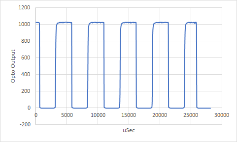
I have a zero cross detection circuit built with a HCPL-817 which is powered on by a AQH3223 SSR. Pin 12 (zeroOnPin) drives the SSR and pin 2 (zeroInputPin) is the input for the circuit to the Arduino.
There is an interrupt when the state of zeroOnPin changes which runs a function that first reads the state of zeroOnPin. If the state is 0 then it is the start of the work half period, there is interrupt timer set up TimerOne.h to delay a set amount of time determined by 'level' then the pump SSR is turned on. If the state of zeroOnPin is 1 then it is the start of the non-work half period and the pump is turned off in the middle of the half period to avoid voltage spikes.
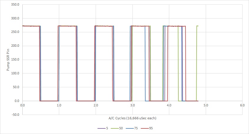
The problem is that no matter where I set the power on delay with the level setting, I get the same output from the pump, except for 0 which turns the pump off. So, 1-100 seems to be full power and 0 is off.
I have tried switching the 0 and 1 arguments against the zeroInputPin in PumpChange() as I don't really know which side of the wave does the work to the same result.
I have inserted serial prints in the PumpStart() and PumpStop() functions and I can see that the commands are being run after each other but I can't tell how long each is on based on the serial output, below is the output. I have added prints for 'timeout_usec' and I can see that the variable is changing with different 'levels'.
I tried entering serial prints with micros() commands in the PumpStart() and PumpStop() functions but that slows the program down.
Can anyone see a flaw in the code? If not do you have any suggestions on how to tell the timing of the PumpStart() and PumpStop() functions so I can diagnose further? I'm out of ideas.
BOM:
Adafruit Metro Mini
IRM-03-05 5v, 600mA AC/DC converter
https://www.digikey.com/en/products/detail/mean-well-usa-inc/IRM-03-5/7704640
AQH3223 Random Fire SSR
https://www.digikey.com/en/products/detail/panasonic-electric-works/AQH3223/2125651
HCPL-817-000E Optoisolator
https://www.digikey.com/en/products/detail/broadcom-limited/HCPL-817-000E/768370
7k resistor
https://www.digikey.com/en/products/detail/vishay-dale/ALSR057K000JE12/257455
1N4007 diode
Arduino Code
#include <Bounce2.h>
#include <TimerOne.h>

#define pumpPin 5
#define zeroInputPin 2
#define brewPin 8
#define zeroOnPin 12

Bounce BrewSwitch = Bounce();

int pumpRunning = 0;

// estimate of lag caused by ZCD circuit in usec
// measured as per http://espresso-for-geeks.kalaf.net/mod-list/#hw-zero-cross
#define ZCD_DELAY 36

// power frequency half-period in usec
#define HALF_PERIOD_USEC 8333

// the time in usec to wait after zero-cross before switching off
// this eliminates the back-EMF by waiting for current to drop before switching off
#define DELAY_AFTER_STOP 4166

// These are precalculated values (usec) of the required phase delays for 0 to 100% power.
// Equation used is: 1000000 usec / 120 * (acos(2*x/100 - 1) / pi)
const uint16_t timeouts_usec[101] =
{ 0, 531, 753, 924, 1068, 1196, 1313, 1421, 1521, 1616,
  1707, 1793, 1877, 1957, 2035, 2110, 2183, 2255, 2324,
  2393, 2460, 2525, 2590, 2654, 2716, 2778, 2839, 2899,
  2958, 3017, 3075, 3133, 3190, 3246, 3303, 3358, 3414,
  3469, 3524, 3578, 3633, 3687, 3740, 3794, 3848, 3901,
  3954, 4007, 4061, 4114, 4167, 4220, 4273, 4326, 4379,
  4432, 4486, 4539, 4593, 4647, 4701, 4755, 4810, 4864,
  4919, 4975, 5031, 5087, 5144, 5201, 5258, 5316, 5375,
  5435, 5495, 5556, 5617, 5680, 5743, 5808, 5874, 5941,
  6009, 6079, 6150, 6223, 6299, 6376, 6457, 6540, 6626,
  6717, 6812, 6913, 7020, 7137, 7265, 7410, 7581, 7802,
  8333
};

int level = 95; //5
uint16_t timeout_usec = HALF_PERIOD_USEC - timeouts_usec[level] - ZCD_DELAY;

void setup() {
  Serial.begin(9600);

  BrewSwitch.attach(brewPin, INPUT_PULLUP);
  BrewSwitch.interval(25);

  pinMode (pumpPin, OUTPUT);

  pinMode (zeroOnPin, OUTPUT);
  digitalWrite(zeroOnPin, LOW);
  pinMode(zeroInputPin, INPUT_PULLUP);

  attachInterrupt(digitalPinToInterrupt(zeroInputPin), PumpChange, CHANGE);
  Timer1.initialize();
}

void loop() {
  checkSwitch();
}

void PumpStart() {
  if (pumpRunning == 1) {
    digitalWrite(pumpPin, HIGH);
    //   Serial.println("on");
    Timer1.stop();
  }
}

void PumpStop() {
  digitalWrite(pumpPin, LOW);
  Timer1.stop();
  //    Serial.println("off");
}

void PumpChange() {
  if (digitalRead(zeroInputPin) == 0) {
    if (level == 100) PumpStart();
    else if (level == 0) PumpStop();
    else {
      Timer1.setPeriod(timeout_usec);
      Timer1.attachInterrupt(PumpStart);
      Timer1.start();
    }
  }

  if (digitalRead(zeroInputPin) == 1) {
    Timer1.setPeriod(DELAY_AFTER_STOP);
    Timer1.attachInterrupt(PumpStop);
    Timer1.start();
  }
}

void checkSwitch() {
  BrewSwitch.update();
  if ( BrewSwitch.fell()) {
    digitalWrite(zeroOnPin, HIGH);
    pumpRunning = 1;
  }
  if ( BrewSwitch.rose()) {
    digitalWrite(pumpPin, LOW);
    digitalWrite(zeroOnPin, LOW);
    pumpRunning = 0;
  }
}
Serial Print PumpStart() and PumpStop() Output
15:51:39.842 -> off
15:51:39.842 -> on
15:51:39.842 -> off
15:51:39.842 -> on
15:51:39.842 -> off
15:51:39.842 -> on
15:51:39.889 -> off
15:51:39.889 -> on
15:51:39.889 -> off
15:51:39.889 -> on
15:51:39.889 -> off
15:51:39.937 -> on
15:51:39.937 -> off
15:51:39.937 -> on
15:51:39.937 -> off
15:51:39.937 -> on
15:51:39.937 -> off
15:51:39.983 -> on
15:51:39.983 -> off
15:51:39.983 -> on
15:51:39.983 -> off
15:51:39.983 -> on
15:51:39.983 -> off
15:51:40.029 -> on
15:51:40.029 -> off
15:51:40.029 -> on
15:51:40.029 -> off
Pressure control circuit diagram.pdf (781 KB)