I am planning to run 2 coreless motors (3A max combined) on 1 irlz44n. I have seperate 3.7v batteries (lipos) for the arduino and the motor. I am using a pro mini 3.3v 8mhz . Will my gate be fully activated if i send a signal?
Since the rds of irlz44n is 5v and the max voltage would be 3.3v..
NO.
You need to find a MOSFET that has a maximum Rds(on) specified for a Vgs of 3.3V or less
Could you suggest one? My requirements are 3.3v rds and 5A cyrrent
It will be a surface mount part.
Try google.
Thats alright
Cheapest I could find in a big package not to hard to solder.
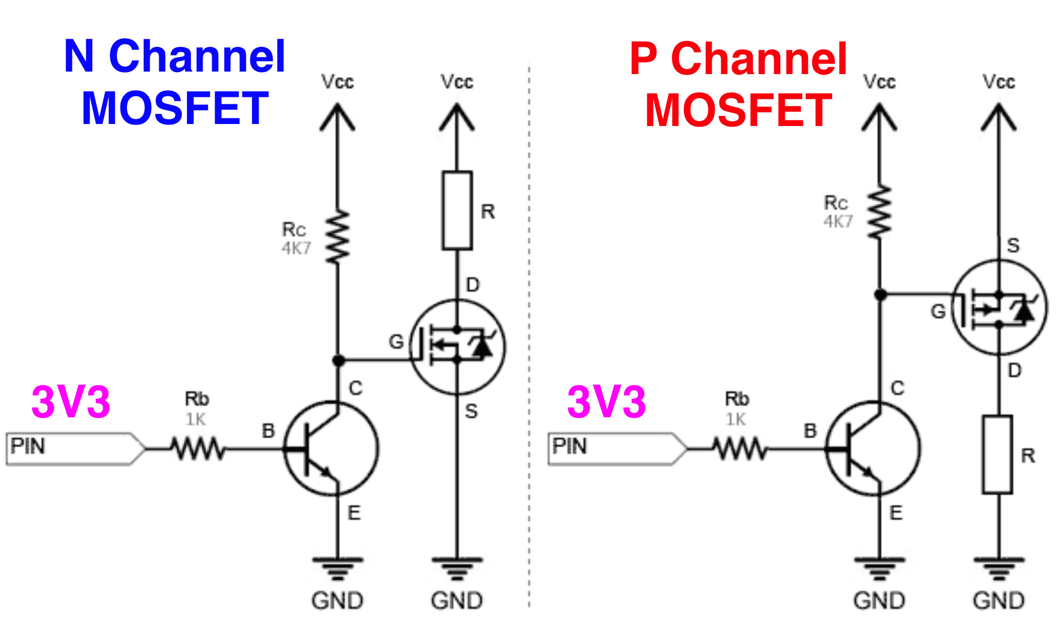
- Drive the MOSFET gate with a BJT.
1 Like

With 3.3v at 3A, the Vds looks like <0.25V, so Rds~0.25/3=0.08ohms. Dissipating 3*3*0.08=0.72W.
It might work.
2 Likes
Never design a circuit based on typical values. There is a 0% chance that the MOSFET you have will be typical. Always use minimum and maximum values, that way you will be 100% sure it will work whether the particular MOSFET you have is actually typical or not.
2 Likes
There is an old saying - "Design with typical values and it will typically fail".
2 Likes
-
Too often we see a design that could be considered boarder line.
-
Many don’t seem to understand they should aways confirm their design to their final circuit by taking voltage and current measurements.
After all, how long does it take to measure the voltage Vds or Vce turn ON voltage ?
5 seconds .
.
1 Like
Never truer word have been spoken!
For my sample of one IRLZ44N, with VGS = 3.0 v, I found Rds = about 0.03 ohms at 100 mA and 500 mA. YMMV.
ETA: FWIW, that Rds is consistent with the slope of the "typical" 3.0 v line in Figure 1 (25 deg C). At 3A, it is probably prudent to use Figure 2 (hotter) to get in the ballpark. But as @LarryD noted, it is simple enough to measure these things...
(oops, meant to reply to the OP... ![]() )
)
1 Like
If you already have the chips you can use a HCT device as a level translator. Run it on 5V drive the gate with it and it is happy with 3V3 logic on the input.
So what is @heckerp1 supposed to do, buy 100 and pick the one that works?
What is so hard with doing it the right way?
- If the OP already has some MOSFETs, yes, they can do some voltage measurements to see if they will work as needed.
- As mentioned, the OP could drive the MOSFET gate with a BJT.
2 Likes
Move to SMD fets. There are plenty of them that can carry 5A+ even with 1.8volt logic.
Leo..
1 Like
I thought @heckerp1's question was more "how will my IRLZ44n with 3.3v signal work for 3.3V @ 3A" rather than "suggest an alternative"
We don't have a schematic, but wouldn't the BJT still only have the same 3.3V battery voltage to switch?
2 Likes