[Solved] LCD is bright but doesn't show text [unsoldered connection]

Arduino beginner here working on a stopwatch, currently the display is very bright but doesn't show the actual text, from what I've been seeing online this is most likely an issue with the potentiometer, no matter how much I move the potentiometer or even remove it nothing happens at all, so that's most likely the issue. I will show you the code and pictures of the actual schematic +a picture of the build on tinkercad where I tested it and without issue and just in case the potentiometer has a 250kΩ value and the resistors have 1kΩ, I can also take a picture of the potentiometer if needed, pretty much all I've done with it is connect the left pin to + right to - and the middle one to V0 of LCD

Here's the code:

#include <LiquidCrystal.h>
LiquidCrystal lcd(12, 11, 5, 4, 3, 2);

int ssButton = 9;
int resButton = 8;

unsigned long startMillis, Sec, Min;

void setup() {
  lcd.begin(16, 2);
  pinMode(ssButton, INPUT);
  pinMode(resButton, INPUT);
  Serial.begin(9600);
  lcd.setCursor(3,0);
  lcd.print("CRONOMETRU");
  lcd.setCursor(5,1);
  lcd.print("00:00");
}

void loop() {
  int val1 = digitalRead(ssButton);
  int val2 = digitalRead(resButton);
  if(digitalRead(ssButton) == 1){
    delay(200);
    lcd.clear();
    lcd.setCursor(3,0);
    lcd.print("CRONOMETRU");
    lcd.setCursor(5,1);
    lcd.print("00:00");
    startMillis = millis();
    while(1){
      if(digitalRead(ssButton) == 1 || digitalRead(resButton) == 1){
        delay(200);
        break;
      }
      Sec = ((millis()-startMillis)/1000)%60;
      Min = ((millis()-startMillis)/60000)%60;
      lcd.setCursor(5,1);
      if(Min < 10){
        lcd.print("0");
        lcd.print(Min);
      }
      else{
        lcd.print(Min);
      }
      lcd.print(":");
      if(Sec < 10){
        lcd.print("0");
        lcd.print(Sec);
      }
      else{
        lcd.print(Sec);
      }
    }
  }
  if(digitalRead(resButton) == 1){
    lcd.setCursor(5,1);
    lcd.print("00:00");
  }
}

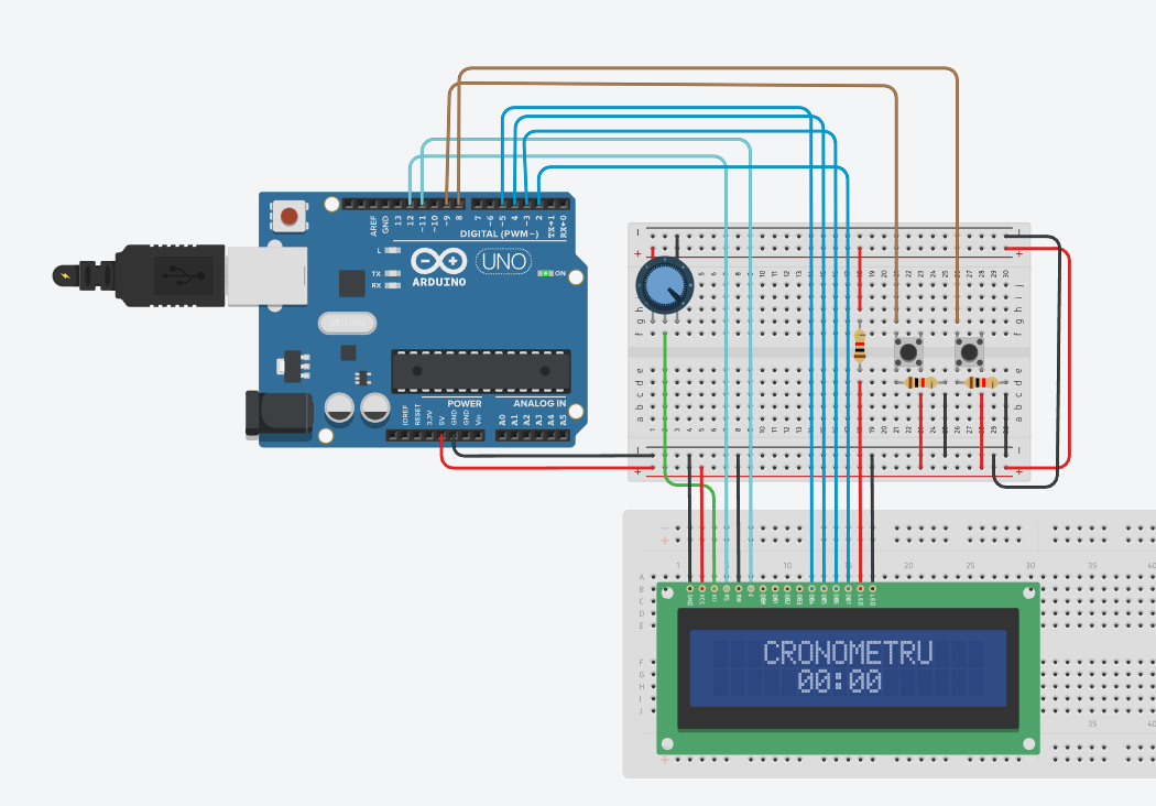
The tinkercad picture of how it should work

The build:


If anyone could help I would be really grateful.

The problem could be anything to do with the wiring or code.

The best approach is to follow one or more of the getting started tutorials. Use the specified wiring and example code to get just one line to be displayed properly, before adding your own code.

Also, you need to carefully solder header pins to the display. You cannot expect breadboard pin connectors to work, if those are being used as suggested by the photo below:

Capture

2 Likes

I heard about the soldering but I don't currently have the means to do it, can it not work like this at all?
Also, the code should be fine since I tested it on a few sites

Not usefully. Learning to solder is a basic requirement for these sorts of projects. Adafruit and Sparkfun have good tutorials on soldering.

You can buy displays and sensor modules with "no solder" connectors, for example using the Adafruit STEMMA system, but then you also need to buy all the matching STEMMA connecting cables.

No.

1 Like

Alright, I will give you guys an update after I manage to solder it somehow, thank you.

Hello ghita13332

You could invest some money into an I²C adapter for LCD to save time and nerves.

You could buy an LCD with a i2c backpack already soldered on it.
This will be easier to hookup and will only use 2 arduino pins.
Then use the hd4480 library and it will discover the i2c address and figure out the pin mappings for you.

--- bill

Hey guys, just a quick update, I got the lcd soldered to the breadboard and everything works just fine now, thank you for the help!

1 Like

This topic was automatically closed 180 days after the last reply. New replies are no longer allowed.