[SOLVED] Waveshare Pico-ePaper-2.13 on Arduino Pro Mini 3.3V with GxEPD2 library

To @ZinggJM , this is a reaction to post #3393.

Hello Jean-Marc,

It took me a while due to a delay in the shipping of the programmer for the Arduino Pro Mini, but here I am finally back with some feedback! In short, the GxEPD2_HelloWorld example works (I am so happy, thanks for helping me on this!!!), but there are some things that I cannot explain. Here below the details.

I have connected the Arduino Pro Mini with the display as follows:

BUSY -> 7
RST  -> 9
DC   -> 8
CS   -> 10
CLK  -> 13
DIN  -> 11
VSYS -> Vcc
GND  -> GND

See also figure:

I have compiled and uploaded the GxEPD2_HelloWorld example from the library (version 1.5.2) with the following changes:

In GxEPD2_display_selection_new_style.h:

#define GxEPD2_DRIVER_CLASS GxEPD2_213_BN // DEPG0213BN 128x250, SSD1680, TTGO T5 V2.4.1, V2.3.1

To get some extra information, I have added in GxEPD2_HelloWorld.ino, just at the beginning of the void setup() function and just before the call to "display.init(115200, true, 2, false);":

void setup()
{
  Serial.begin(115200);
  Serial.println();
  Serial.println("setup");
  delay(100);
  //display.init(115200); // default 10ms reset pulse, e.g. for bare panels with DESPI-C02
  display.init(115200, true, 2, false); // USE THIS for Waveshare boards with "clever" reset circuit, 2ms reset pulse
  helloWorld();
  display.hibernate();
}

After uploading, I didn't see any reactions from the display, I could see however the following on the serial monitor (this goes in an endless loop, I am just coping the initial part):

14:08:29.207 -> 
14:08:29.207 -> setup
14:08:30.772 -> 
14:08:30.772 -> setup
14:08:32.335 -> 
14:08:32.335 -> setup
14:08:33.898 -> 
14:08:33.898 -> setup
14:08:35.461 -> 
14:08:35.461 -> setup

It seems that, every time the call to

display.init(115200, true, 2, false);

is reached, the program crashes (?) and it starts again from the beginning, thus by printing again the string "setup". It seems that this takes approximately 1.5 s.

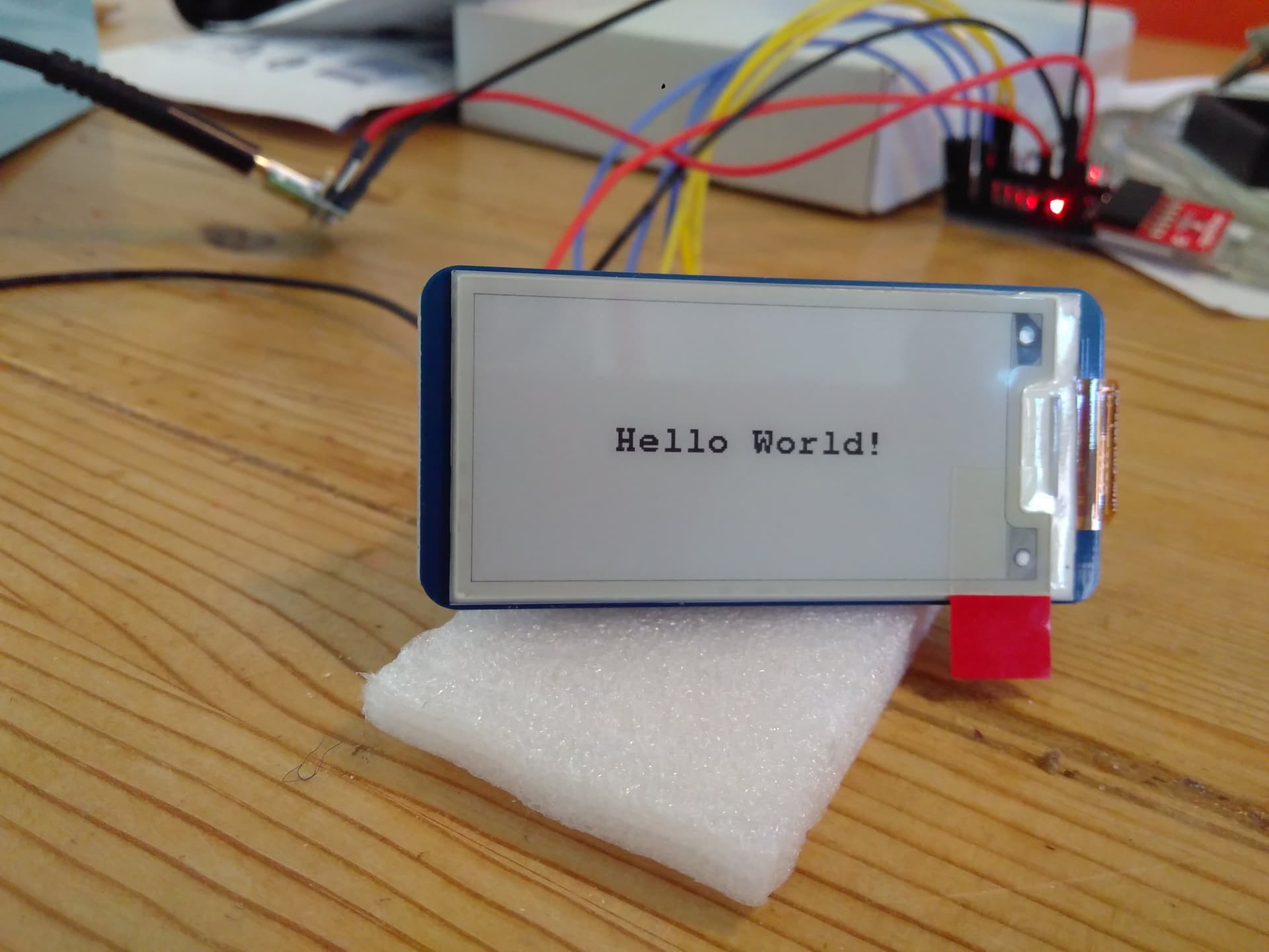
Later, just by chance, it happened to me to repeat the same process but with the VSYS -> Vcc disconnected. Now the GxEPD2_HelloWorld works and I see appearing on the display the "Hello World!" string. From the serial monitor the following appears:

14:11:58.152 -> 
14:11:58.152 -> setup
14:11:58.417 -> _PowerOn : 94248
14:12:04.401 -> _Update_Full : 5224480
14:12:04.933 -> _PowerOff : 79592

So, I cannot explain to myself how it is possible that it works only when I disconnect the power!? I am very curious if you have perhaps any ideas on this?

Perhaps good to mention: you had already found the display that I am using and you reported the following link:

https://nl.aliexpress.com/item/1005002121960368.html?gatewayAdapt=glo2nld

and you indicated that the inking on the flex connector is FPC-7528, indeed from that site I see the same: FPC-7528 S (I don't know if the extra "S" matters). Now I also have physically looked at my display, there on the flex connector is given:

HINK-E0213A22-AO
SLH 1948

See also figure:

which is different. Does it make sense to you? I don't know how to interpret these codes.

So if you would have any ideas, please let me know! Thanks in advance for your great help!

Regards,
Carlo

@carlo_lugaro, Hi Carlo,

I would need a link or a schematic of your USB to Serial converter to know for sure.
I assume it feeds 3.3V through its LDO to your Arduino Pro Mini 3.3V.
These usually have weak LDOs (I had some bad experience with also) that barely can feed a Pro Mini, but not added peripherals.

You most likely encounter brown out reset of the Pro Mini, as soon as the voltage booster of the display is started.
If you disconnect VSYS, input to the "clever" reset circuit, then the controller is only fed through the data lines, weakly and with lower voltage, which reduces the (inrush) current drawn.
I am surprised that the display works with this, but it is not healthy for the controller.
-jz-

Hi Jean-Marc!

That makes sense! The USB to Serial converter is a SparkFun FTDI Basic Breakout - 3.3V:

https://www.sparkfun.com/products/9873

Here the schematics:

https://cdn.sparkfun.com/datasheets/BreakoutBoards/FTDI%20Basic-v22-3.3V.pdf

From the specs I see that it uses the FT232RL:

https://ftdichip.com/wp-content/uploads/2020/08/DS_FT232R.pdf

From there, at page 7, it indicates that it can provide 50 mA current:

+3.3V output from integrated LDO regulator. This pin should be
decoupled to ground using a 100nF capacitor. The main use of this pin is
to provide the internal +3.3V supply to the USB transceiver cell and the
internal 1.5kΩ pull up resistor on USBDP. Up to 50mA can be drawn from
this pin to power external logic if required. This pin can also be used to
supply the VCCIO pin.

To me it would seem that it should be enough, but I cannot really say. What I will do, I will try to power the display with a separate voltage regulator. I will let you know how it will go!

Thanks!
Carlo

Hello Jean-Marc,

I am feeding now the Arduino Pro Mini with 5V input to the RAW input and now indeed the display also works when I connect the 3.3V Vcc to VSYS! So this confirms your previous explanation. So great!

Now I am struggling however with the fact that it seems that only a full update works, the partial update gives strange results. From the specs of the display (https://nl.aliexpress.com/item/1005002121960368.html?gatewayAdapt=glo2nld), it seems that it should support the partial update. I have seen that there are a few other posts that relate to problems with the partial update and so I will dig into them but, if you perhaps would already have an idea on what it could be going wrong here, I would be happy to know from you! So, in case, here below the details.

I am running the GxEPD2_Example with, as usual, in GxEPD2_display_selection_new_style.h:

#define GxEPD2_DRIVER_CLASS GxEPD2_213_BN // DEPG0213BN 122x250, SSD1680, (FPC-7528B), TTGO T5 V2.4.1, V2.3.1

and where I have commented in GxEPD2_Example.ino in void setup() all calls except the ones to helloWorld(); and helloValue(123.9, 1);. Basically, printing a value on the display is what I ultimately need. Here below the void setup() that I am running:

void setup()
{
  Serial.begin(115200);
  Serial.println();
  Serial.println("setup");
  delay(100);
#if defined(ARDUINO_ARCH_RP2040) && defined(ARDUINO_RASPBERRY_PI_PICO)
  // uncomment next line for use with GoodDisplay DESPI-PICO, or use the extended init method
  //display.epd2.selectSPI(SPI0, SPISettings(4000000, MSBFIRST, SPI_MODE0));
  // uncomment next 2 lines to allow recovery from configuration failures
  pinMode(15, INPUT_PULLUP); // safety pin
  while (!digitalRead(15)) delay(100); // check safety pin for fail recovery
#endif
#if defined(ESP32) && defined(USE_HSPI_FOR_EPD)
  hspi.begin(13, 12, 14, 15); // remap hspi for EPD (swap pins)
  display.epd2.selectSPI(hspi, SPISettings(4000000, MSBFIRST, SPI_MODE0));
#endif
  //display.init(115200); // default 10ms reset pulse, e.g. for bare panels with DESPI-C02
  display.init(115200, true, 2, false); // USE THIS for Waveshare boards with "clever" reset circuit, 2ms reset pulse
  //display.init(115200, true, 10, false, SPI0, SPISettings(4000000, MSBFIRST, SPI_MODE0)); // extended init method with SPI channel and/or settings selection
  // first update should be full refresh
  helloWorld();
  delay(1000);
  // partial refresh mode can be used to full screen,
  // effective if display panel hasFastPartialUpdate
  //helloFullScreenPartialMode();
  //delay(1000);
  //stripeTest(); return; // GDEH029Z13 issue
  //helloArduino();
  //delay(1000);
  //helloEpaper();
  //delay(1000);
  helloValue(123.9, 1);
  delay(1000);
  //showFont("FreeMonoBold9pt7b", &FreeMonoBold9pt7b);
  //delay(1000);
  //if (display.epd2.WIDTH < 104)
  //{
  //  showFont("glcdfont", 0);
  //  delay(1000);
  //}
  //drawBitmaps();
  //drawGraphics();
  //return;
#if !defined(__AVR) // takes too long!
  //if ((display.epd2.panel == GxEPD2::ACeP565) || (display.epd2.panel == GxEPD2::GDEY073D46))
  //{
  //  //draw7colorlines();
  //  //delay(2000);
  //  draw7colors();
  //  delay(4000);
  //}
#endif
  //if (display.epd2.hasPartialUpdate)
  //{
  //  showPartialUpdate();
  //  delay(1000);
  //} // else // on GDEW0154Z04 only full update available, doesn't look nice
  ////drawCornerTest();
  ////showBox(16, 16, 48, 32, false);
  ////showBox(16, 56, 48, 32, true);
  display.powerOff();
  //deepSleepTest();
#if defined(ESP32) && defined(_GxBitmaps1304x984_H_)
  //drawBitmaps1304x984();
  //display.powerOff();
#endif
  Serial.println("setup done");
}

When I run it, this is what I get on the serial monitor:

11:49:34.720 -> 
11:49:34.720 -> setup
11:49:34.952 -> _PowerOn : 94216
11:49:40.462 -> _Update_Full : 5224616
11:49:40.761 -> _PowerOff : 79560
11:49:41.922 -> _PowerOn : 94192
11:49:44.910 -> _Update_Part : 2934656
11:49:49.988 -> _Update_Part : 2934656
11:49:51.150 -> _PowerOff : 79536
11:49:51.150 -> setup done

Now, just after the call to helloWorld(), the display correctly outputs "Hello World!", which corresponds in time to the

11:49:40.462 -> _Update_Full : 5224616

on the serial monitor. See also picture below:

But then just after the call to helloValue(123.9, 1), which corresponds in time to the

11:49:44.910 -> _Update_Part : 2934656
11:49:49.988 -> _Update_Part : 2934656

on the serial monitor, the number "123.9" does not appear as I would expect. Instead, a strange grayish border on the screen appears. Se also picture below:

In principle, I don't mind too much for the grayish border, but I would like to have the number to appear on the display!

This happens in general, at any time a partial update is applied (for example from other functions in GxEPD2_Example), only this gray border appears.

So, if you would have any ideas here, it would be very much appreciated! Meanwhile, I continue digging in the posts and doing some experiments.

Thanks in advance!

Regards,
Carlo

These values are totally different from the values I measured for this display:

    static const uint16_t power_on_time = 100; // ms, e.g. 95868us
    static const uint16_t power_off_time = 250; // ms, e.g. 140350us
    static const uint16_t full_refresh_time = 4100; // ms, e.g. 4011934us
    static const uint16_t partial_refresh_time = 750; // ms, e.g. 736721us

from https://github.com/ZinggJM/GxEPD2/blob/master/src/epd/GxEPD2_213_BN.h

The full refresh time can be different, as this wavetable comes from OTP. And it is temperature dependent.
But the differential refresh time should be identical, as the wavetable is set to controller registers for this display, as it has no wavetable for differential refresh in OTP.

Are you sure you uncommented only the line for this display to select?

The inking doesn't correspond to the display you selected.

Added: I suggest your try this display with the Waveshare demo code, just to see if it works with this code.

Hello Jean-Marc,

I think so, but perhaps let's double check to be sure. I have uncommented one line only in file GxEPD2_display_selection_new_style.h:

#define GxEPD2_DRIVER_CLASS GxEPD2_213_BN // DEPG0213BN  122x250, SSD1680, (FPC-7528B), TTGO T5 V2.4.1, V2.3.1

Is this correct? Or are there other files or sections in this file that need to be configured? To double check, in GxEPD2_EPD.cpp in the definition of _waitWhileBusy, just after:

        Serial.print(comment);
        Serial.print(" : ");
        Serial.println(elapsed);

I have added the following:

        Serial.print(" : ");
        Serial.println(busy_time);

Now the serial monitor output is:

16:31:59.161 -> 
16:31:59.161 -> setup
16:31:59.427 -> _PowerOn : 94200
16:31:59.460 ->  : 100
16:32:04.943 -> _Update_Full : 5224632
16:32:04.943 ->  : 4100
16:32:05.242 -> _PowerOff : 79544
16:32:05.242 ->  : 250
16:32:06.372 -> _PowerOn : 94168
16:32:06.372 ->  : 100
16:32:09.362 -> _Update_Part : 2934640
16:32:09.362 ->  : 750
16:32:14.444 -> _Update_Part : 2934648
16:32:14.444 ->  : 750
16:32:15.607 -> _PowerOff : 79528
16:32:15.607 ->  : 250
16:32:15.607 -> setup done

where the values of busy_time correspond with the ones defined in GxEPD2_213_BN. So, this seems OK to me.

This is a point that perhaps needs some attention. I have uncommented the GxEPD2_213_BN, based on the link https://www.aliexpress.com/item/1005002121960368.html where from the photo it is visible the code FPC-7528. But, looking physically at the display that I own, this other code is indicated:

HINK-E0213A22-AO
SLH 1948

See also:

Perhaps I should not use GxEPD2_213_BN but another one? I don't know how to interpret these codes. What is your opinion on this? How can I determine which driver shall I use, depending on the code on the flex connector?

Note added later: I think that I have just found out how you can determine the driver based on the inking: you have indicated these codes in the comments in GxEPD2_display_selection_new_style.h. It was too easy, sorry for my silly question above :slight_smile: . In any case there I have found two similar codes:

//#define GxEPD2_DRIVER_CLASS GxEPD2_213_B72 // GDEH0213B72 122x250, SSD1675A (IL3897), (HINK-E0213A22-A0 SLH1852)
//#define GxEPD2_DRIVER_CLASS GxEPD2_213_B73 // GDEH0213B73 122x250, SSD1675B, (HINK-E0213A22-A0 SLH1914)

but not 100% identical to mine. Could it be that my display is just not supported by the GxEPD2 library? Do you think that I could just try these two that are similar, or are there any risks to damage the display?

Thanks for this explanation! However, due to my limited knowledge on this topic, I cannot fully understand. But perhaps this is more of a detail that for the moment I don't really need to understand ...

That is a good suggestion! Just when I had ordered the displays (I ordered 2x this model in BW and 1x another model in color) I tried the Waveshare demo code on the color model and it worked. Now I wanted to test it also with the BW, but somehow the tutorial for the arduino disappeared from the Waveshare site (https://www.waveshare.com/wiki/Pico-ePaper-2.13). I have just sent a support request to Waveshare for this and I will try their demo code as soon as I get a reaction from their support.

Yes, this is possible. As you found out, there are several displays with almost same inking.
The two you mention have different controllers!
The last token seems to be a sort of serial number.

Yes, you can, and you should. There is almost no risk, at least within same size (small or big) and same controller family (SSD). Don't let it run for extended time period, if picture is bad, to reduce risk of permanent ghosting.

The fact that it is different may indicate that the controller may be different. Either doesn't understand the wavetable used, or misinterprets it.

https://www.waveshare.com/wiki/Pico-ePaper-2.13 works for me.

I tried the GxEPD2_213_B72 and this one works!!!

Here the output from the serial monitor when I run GxEPD2_Example from the library:

19:19:38.562 -> 
19:19:38.562 -> setup
19:19:38.828 -> _PowerOn : 89984
19:19:40.921 -> _Update_Full : 1669216
19:19:41.253 -> _PowerOff : 170576
19:19:42.449 -> _PowerOn : 89992
19:19:43.047 -> _Update_Part : 190504
19:19:44.874 -> _Update_Part : 190480
19:19:47.366 -> _Update_Part : 190440
19:19:51.286 -> _Update_Full : 1669320
19:19:52.548 -> _PowerOff : 170576
19:19:53.678 -> _PowerOn : 90032
19:19:55.606 -> _Update_Full : 1669288
19:19:56.038 -> _PowerOff : 170616
19:19:56.171 -> _PowerOn : 90000
19:19:57.965 -> _Update_Full : 1669312
19:19:58.331 -> _PowerOff : 170560
19:19:58.497 -> _PowerOn : 89984
19:19:58.862 -> _Update_Part : 190432
19:20:01.587 -> _Update_Part : 190440
19:20:03.314 -> _Update_Part : 190456
19:20:06.072 -> _Update_Part : 190464
19:20:07.833 -> _Update_Part : 190480
19:20:10.591 -> _Update_Part : 190528
19:20:12.351 -> _Update_Part : 190472
19:20:15.109 -> _Update_Part : 190488
19:20:16.870 -> _Update_Part : 190496
19:20:18.166 -> _Update_Part : 190512
19:20:19.496 -> _Update_Part : 190504
19:20:20.791 -> _Update_Part : 190520
19:20:22.121 -> _Update_Part : 190504
19:20:23.417 -> _Update_Part : 190464
19:20:24.713 -> _Update_Part : 190528
19:20:26.041 -> _Update_Part : 190528
19:20:27.369 -> _Update_Part : 190504
19:20:28.698 -> _Update_Part : 190400
19:20:30.989 -> _Update_Part : 190464
19:20:32.749 -> _Update_Part : 190464
19:20:34.112 -> _Update_Part : 190472
19:20:35.408 -> _Update_Part : 190504
19:20:36.771 -> _Update_Part : 190416
19:20:38.101 -> _Update_Part : 190448
19:20:39.463 -> _Update_Part : 190488
19:20:40.792 -> _Update_Part : 190488
19:20:42.155 -> _Update_Part : 190488
19:20:43.485 -> _Update_Part : 190520
19:20:44.849 -> _Update_Part : 190464
19:20:47.174 -> _Update_Part : 190408
19:20:48.970 -> _Update_Part : 190448
19:20:50.298 -> _Update_Part : 190456
19:20:51.627 -> _Update_Part : 190440
19:20:52.988 -> _Update_Part : 190456
19:20:54.351 -> _Update_Part : 190472
19:20:55.680 -> _Update_Part : 190488
19:20:57.043 -> _Update_Part : 190472
19:20:58.372 -> _Update_Part : 190496
19:20:59.767 -> _Update_Part : 190464
19:21:01.095 -> _Update_Part : 190472
19:21:03.418 -> _Update_Part : 190472
19:21:05.213 -> _Update_Part : 190448
19:21:06.541 -> _Update_Part : 190472
19:21:07.904 -> _Update_Part : 190504
19:21:09.234 -> _Update_Part : 190520
19:21:10.563 -> _Update_Part : 190456
19:21:11.891 -> _Update_Part : 190504
19:21:13.220 -> _Update_Part : 190416
19:21:14.549 -> _Update_Part : 190432
19:21:15.912 -> _Update_Part : 190504
19:21:17.274 -> _Update_Part : 190464
19:21:19.568 -> _Update_Part : 190432
19:21:22.026 -> _PowerOff : 170632
19:21:22.159 -> _PowerOn : 90000
19:21:23.955 -> _Update_Full : 1669304
19:21:24.320 -> _PowerOff : 170608
19:21:24.486 -> _PowerOff : 170552
19:21:29.635 -> _PowerOn : 90024
19:21:31.562 -> _Update_Full : 1669296
19:21:31.994 -> _PowerOff : 170576
19:21:37.112 -> _PowerOn : 89960
19:21:38.972 -> _Update_Full : 1669264
19:21:39.371 -> _PowerOff : 170576
19:21:39.571 -> _PowerOff : 170552
19:21:39.571 -> setup done

and on the display everything appears the way I think it should be. Just out of curiosity, I have also tried GxEPD2_213_B73: this one gives strange results.

So now I have a base to start coding starting from your example and I should be able to proceed on my own.

At this point I think that we can mark this topic as solved. But before that: do you need any information out of this exercise or shall I run any other tests that might be helpful for you?

In any case, thank you so much! Not only for coding this useful library but also for providing support in such an efficient way!

Carlo

Thank you for the feedback! That's all I need to know. I am surprised that they put that rather old panel on this quite new display board. Maybe you got one from a test production series.

Yes, that is strange indeed. The shop where I had ordered from has a good reputation and I have ordered from them in the past, but who knows. Anyway, now I have a working setup and I am just so happy for this!

Note that it is good practice to mark one post as the solution to your question(s).

Thanks for the tip, just did it. I am still new on this forum, so still learning :slight_smile:

This topic was automatically closed 180 days after the last reply. New replies are no longer allowed.