I've been trying to read samples from a microphone with my Arduino Due. Somehow the samples are wrong in amplitude and I can't figure out how they end up that way.
Setup is as follows:
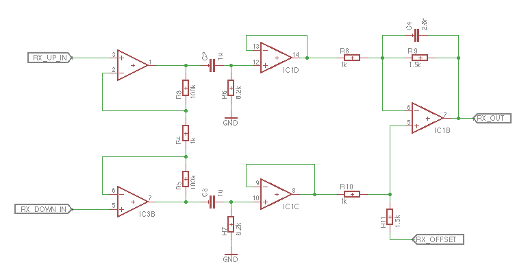
Microphone -> filter to make sure the signal is in the range 0-3.3 V -> Arduino Due ADC.
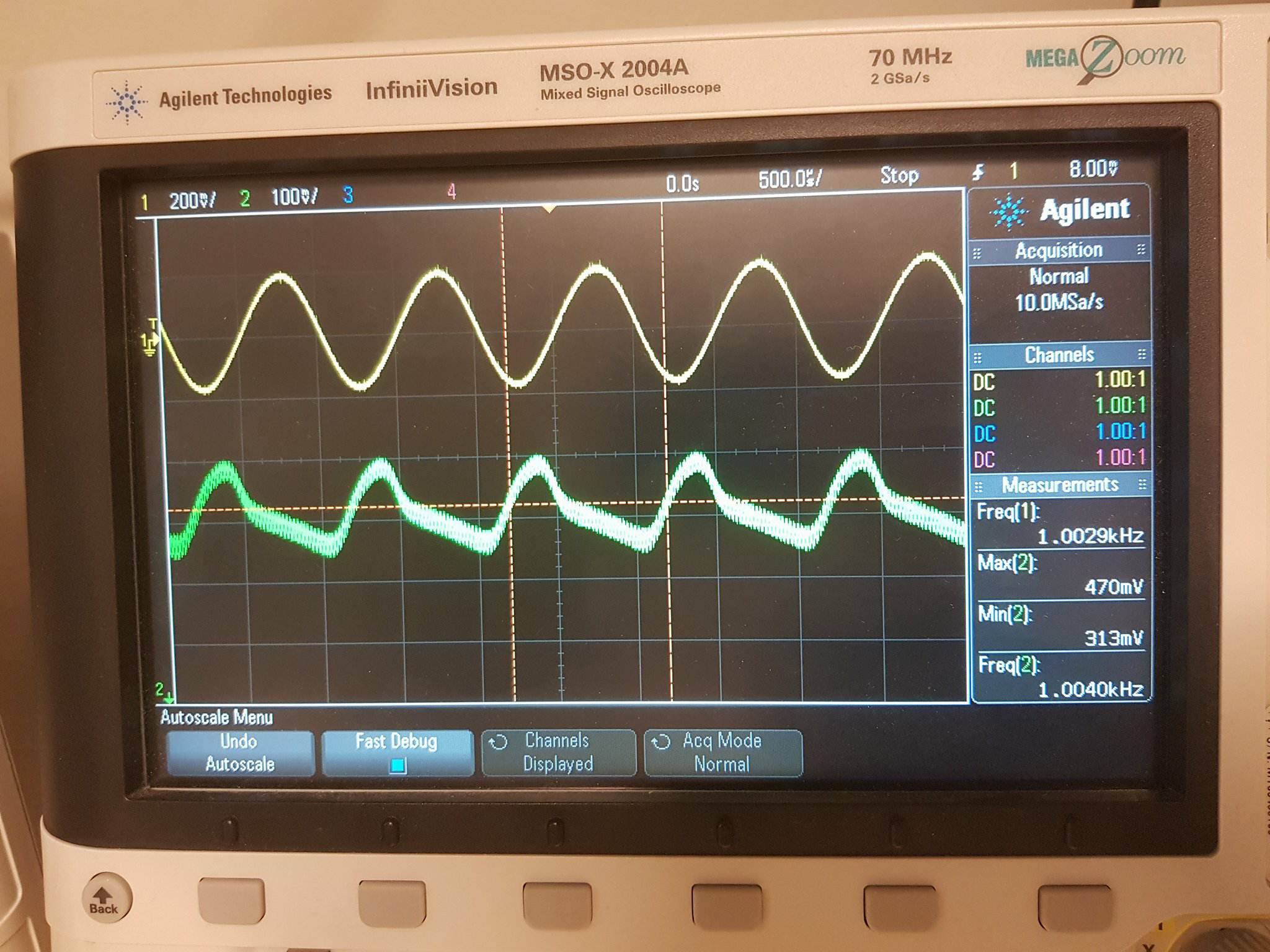
I play a sine with frequency of 1000 Hz to the microphone and measure the output on my oscilloscope. The picture below shows the signal before (yellow) and after (green) my filter. The filter is not the best but that is not important here.

The sampled signal on my Arduino Due is sampled with 48 kHz. In the end my Arduino will take input from 8 different microphones. For now I just feed the same signal (the green one from the picture) to all 8 ADC channels.
This picture below this paragraph shows 1024 samples on channel0 and channel7 (red and blue) that I've sent from the Arduino Due to MATLAB using a USB serial connection. (The figure also shows the difference between the signals in green.) As seen the signals are not completely identical but that's not important to the main problem, although not ideal for the end goal.
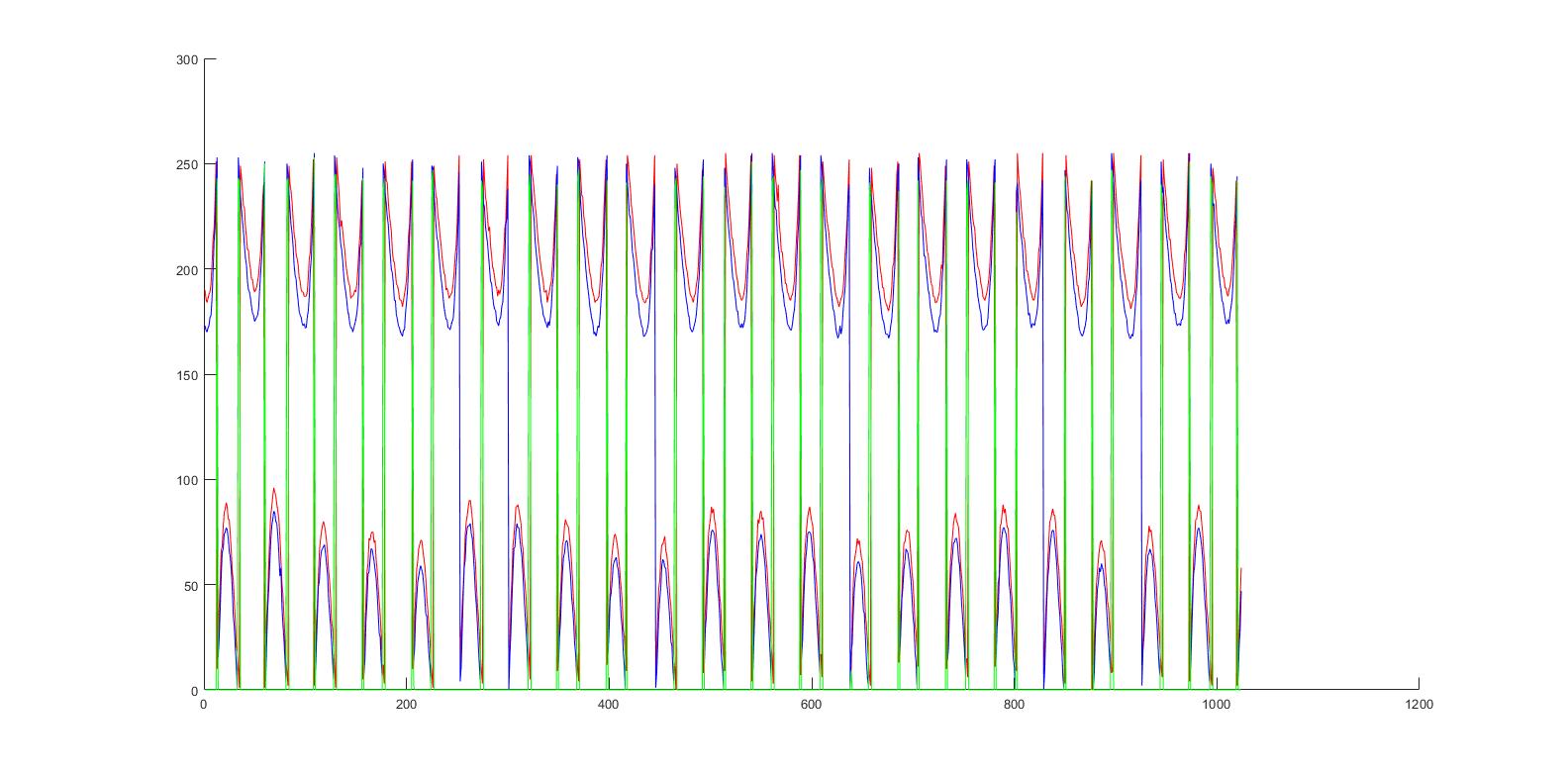
There is obviously something wrong here. According to my calculations the green signal on the oscilloscope has a peak-to-peak 0.470-0.313 V (readings from the Measurements tab down right on the oscilloscope) which is 0.157 V.
In my sketch I set the analog read resolution to 8 bits using
analogReadResolution(8);
1 bit then corresponds to 3.3/256 = 0,0129 V/bit. Since signal peak-to-peak is 0.157 V it would correspond to a very small signal, read by the ADCs, fluctuating with 0.157/0,0129 = 12 bits in the lower region of the plot. This is not the case as seen in the picture above, the signal amplitude covers almost the whole 256 value range and is overflowing resulting in going from 255->0 over all periods. Is there something I missed?
To be clear, the period of the recorded signal is very satisfying. I've counted the number of samples in the period of the signal in the plot. They are (on average taken over all the displayed periods) almost exactly 48. Since sampling frequency is 48 000 we get the frequency of the recorded signal to 1/(48/48 000) = 1000 Hz.
I've done this test with a lot of different frequencies and its the same type of result.
I attached the images together with the source code. It's 2 sketches, one for the Arduino Due that is sampling the signal, one for the Arduino Due that send's the 48 kHz interrupt-sampling-signal, and the MATLAB code, RecordSamples.m file and a SerialSetup.m script (uploaded as .pdfs here).
The way the sampling works is that one Arduino sends an interrupt signal at 48 kHz to the sampling Arduino, that is because in the end I will have 8 Arduinos recording on 8 channels, that is 64 different microphones. And they all need to record at the same time (+- the time for all 8 channels to take a sample within one Arduino). The sampling needs to be very quick that's why I've had to use register calls rather than normal Arduino wrapping code.
The way I see it it could be 2 things going wrong here
-
Some data type conversion is made wrong somewhere, overflowing the uint8 type, resulting in a weird amplitude but correct period. If so I'd be happy if someone could point to where.
-
Maybe the ADC doesn't read 8-bit, but some larger value that will overflow the 8-bit conversion again resulting in a weird amplitude but correct period. If so maybe someone could explain why, and how to correct it.
I hope the problem is understandable and I hope you will want help me pinpoint the problem or suggest a solution  I've spent the better part of the day searching for an answer.
Here is the code for the sampling Arduino in text format as well:
volatile int sampleCount = 0;   //count samples so we don't get more than 1024
volatile bool measure = false;  //flag to decied if we want to sample or not

const byte interruptPin = 2;    //the interruptsignal comes to this pin

const int channels = 8;                         //the number of analog channels to record on
const int sampleMax = 1024;                     //length of the sample array
uint8_t recordedSamples[channels][sampleMax];   //2D array to store the sampled signals in

void setup() {
  //set interrupt pin
  pinMode(interruptPin, INPUT_PULLUP);
  attachInterrupt(interruptPin, readSample, RISING);

  //ADC setup
  ADC->ADC_MR |= 0x80;  //set free running mode on ADC
  ADC->ADC_CHER = 0xFF; //enable ADC on pin A0-A7
  analogReadResolution(8); //<---- this seems to be ignored

  //serial setup and send ready message to MATLAB
  Serial.begin(250000);
  Serial.println("Slave ready");
}

void loop() {
  //In the main loop there is a while loop that checks for serial commands
   while (Serial.available() > 0) {
      //reads a byte from Serial. This byte is a "command" byte telling us  what to do
     char ans=Serial.read();
      if(ans=='r')
      {//In this case MATLAB wants us to begin reading samples
        //and listen to interrupts, 'a' is confirmation char in this case
        sampleCount = 0;
        Serial.write('a');
        measure = true;   //sets the flag to begin listen to interrupts
      }else if(ans == 'd')
      { //In this case MATLAB wants us to send the recorded signals on channel 0 and 7
        Serial.write(recordedSamples[0], sampleMax);
        Serial.write(recordedSamples[7], sampleMax);
      }
   }

}

//This is the interrupt function
void readSample(){
  if (!measure) return;           //if this flag is false we dont want to begin sampling yet
  if (sampleCount >= sampleMax){  //if we've reached the end of sampling array we dont want to sample anymore
    measure = false;
    Serial.write('r');
    return;
  }

   while((ADC->ADC_ISR & 0xFF)==0); // wait for conversion

   for(int i=0; i<channels; i++){                     //goes through the channels
    recordedSamples[i][sampleCount]= ADC->ADC_CDR[i]; //read values into array
   }

   sampleCount++;                                     //increment what sample we are taking next time
}

clock_generator.ino (1.72 KB)
RecordSample.ino (2.27 KB)
RecordSamples.pdf (7.86 KB)
serialsetup.pdf (6.61 KB)