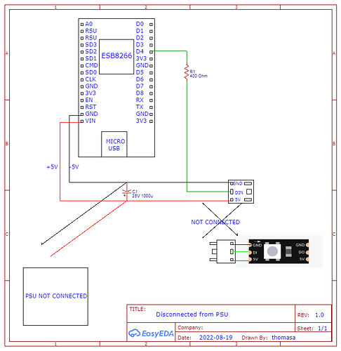
I'm new to electronics and I wanted to do just to make a very simple circuit to a WS2812B LED strip with an ESP8266 board, all running on 5v. I was possibly going to change some things in the future for other projects. The ESP8266 was powered through the VIN pin which I read was able to be powered at 5V.
I believe I made two mistakes the end result being I smoked a diode on the board, the board will still power up but will not connect through the micro USB. I'm counting this board as a loss.
What I would like to know is what the culprit was for why that happened.
The circuit I built looked like this when it was connected to the PC to be coded, it was not connected to external power or an LED strip. It was connected to a 25v 1000uF capacitor.
Edit: its supposed to be 330 ohm not 400, sorry
(sorry for the crudeness of the picture)
What I'm thinking happened was the capacitor was drawing too much current through the VIN pin which destroyed the diode on the ESB8266 or it was the second mistake I made which was when I soldered my wire to the ESB8266 I put heat shrink over the wires to keep the GND and VIN pins from touching. I accidentally covered the GND and the RST with the heat shrink and I believe the pins may have had contact with each other.
I'm not sure what broke it but I think it was one of those two, if not both. Any input is greatly appreciated!
Just incase anyone was wondering, this was the code I was going to be using. This should work.
I didn't get the chance to upload it before it broke
#include <FastLED.h>
#define LED_PIN 4
#define NUM_LEDS 300

CRGB leds[NUM_LEDS];

void setup() {
  // put your setup code here, to run once:
FastLED.addLeds<WS2812B, LED_PIN, GRB>(leds, NUM_LEDS);
FastLED.setMaxPowerInVoltsAndMilliamps(5, 170);
FastLED.clear();
FastLED.show();
}

void loop() {
  // put your main code here, to run repeatedly:
//just to make all LEDs red
   for(int i=0; i<300; i++){
    leds[i]=CRGB(255,0,0);
  }

  FastLED.show();

}