void loop() {
// put your main code here, to run repeatedly:
display.clearDisplay();
display.setTextSize(1);
display.setTextColor(WHITE);
display.setCursor(0, 0);
display.print("Wurfergebnis:");
display.drawLine(0, 11, 127, 11, WHITE);
display.display();
}
END
The sketch worked fine with my Arduino Uno :(
I am at a loss where to search for possible faults..
Usually when you buy these devices it's just a matter of connecting it up to your arduino and flashing it with the ada fruit ssd1306 lib 128x84 i2c. But as stated in the instructions it's not an ssd1306 chip its a SH1106 chip.
You need the U8G2 library and you need to un-comment the following line.
missdrew:
Are you sure it's a SSH1106? Could be a SSD1306!
I trief what you suggested, it works with my Arduino Uno Board, but again, the pro Micro is not doing anything.
I'm pretty sure its an SH1106 Display, since it worked perfectly fine until I swaped boards.
That is what i don't understand.
Sketch and Display and wires are working perfectly, I'm starting to think the pro micro is broken
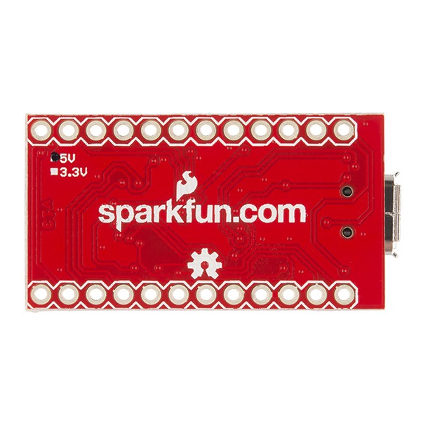
The Pro Micro is available in 2 versions.
A 16 MHz 5 volt version, and a 8 MHZ 3.3 volt version.
Usually there is some indicator on the bottom of it, telling what version you've got:
If you have the 3 volt version, then you aren't communicating with 5 volts and that may be your problem.
A HIGH with a 3v3 system is anywhere between 1.7 and 3.3 volts, with a 5 volt system you'd need at least over 2.6 volts to reach a HIGH.
So you may need to boost the voltage if you have a 3v3 version.
The difference between these 2 Pro Micro versions isn't just the voltage.
The clock speed is more important.
A 16 MHz system is not stable if it is powered with less than 5 volts.
8 MHz allows a 3v3 supply and yet be stable.
The OLED will work fine at 3.3V. After all it is a 3.3V device.
In theory you should short out the AMS1117-3.3 / 662K voltage regulator if you are supplying VCC=3.3V
In practice the AMS1117-3.3 drops an insignificant voltage even when you supply 3.3V. OLED modules will work ok. That is why they are called Low Drop Out regulators.
Yes, the ATmega32U4 is not specced for 16MHz @ 3.3V. But it will work fine for hobbyist use.
The Pro Micro is not sold with 16MHz and 3.3V. The OLED will work fine at 8MHz @ 3.3V
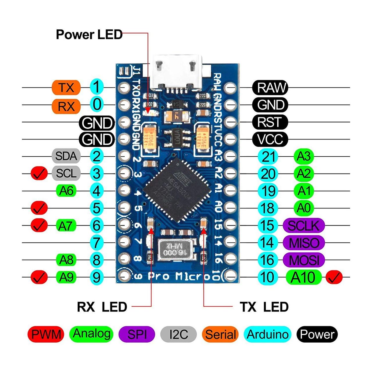
There are only 4 wires to connect the SH1106 module to the Pro Micro.
Until we see a photo we can only assume that you have not connected correctly.
This is how i connected the OLED to the Pro Micro. I also tried a script to show me, if any device is connected to the I2C, but I did not get any result.
Thats why I'm pretty sure, my board is just broken down
So you will have 3.3V on the VCC pin.
And your logic levels are 3.3V
My Leonardo is 16MHz 5V. So I ran the same example sketch on a 3.3V board with VCC=3.3V
And it is working just fine. I have not bypassed the 662K voltage regulator. This shows that the LDO regulator will still provide power even when supplied with 3.3V
Your wiring looks ok.
I suggest that you measure the voltage on the VCC pin.
And test each Dupont wire for continuity.
Check your Pro Micro header strip soldering.
Are the header strip pins engaged with the breadboard?
Remove from breadboard and plug Duponts onto the header pins.
Those pins are on the wrong side (upside down) of the Pro Micro.
Usually the pins are longer on one side, and they'd be soldered at the shorter side so the longer side protrudes more.
If those pins are soldered with the longer side up, don't bother with the breadboard because the pins will not make good contact (if any at all) with the breadboard.
If the pins are longer at the lower side, they may not make good contact too because too much of the pins can be lost this way.
In case the longer side is up, use female-female connectors and connect them to the longer pins, so on the top side of the Pro Micro.
These answers show the importance of good quality and focused photos.
I had some trouble with my OLED displays too (SSD 1306), amongst others with a I2C scanner not finding the display.
My displays have a serial input and a serial output pin, which need to be tied together in case you need to use bidirectional I2C communication, and the supplier didn't bother to do that.
So i had to connect those pins for the scanner to find the board.
The scanner sends some sort of "ping" to an address, and waits for a reply.
If the answer times out, the scanner will try the next address.
If an answer is received, the scanner prints the address and quits.
I changed that scanner so it would not quit, but simply try every address possibly revealing multiple devices.
When the I2C interface is selected, then D0 serves as the serial clock input pad (SCL) and D1 serves as the serial data input pad (SDAI). At this time, D2 to D7 are set to high impedance.
This means a SH1106 isn't capable of bidirectional I2C traffic and cannot reply to the aforementioned "ping".
So you cannot use such tools to find the address of a SH1106.
Yes, some of the first I2C SSD1306 modules came as non-ACK. But that was 5 years ago.
I would expect current SSD1306 modules to behave correctly.
I have never heard of a non-ACK SH1106 module. It is possible.
SH1106 uses the same interface as SSD1306 i.e. D2 connected to D1 for bidirectional SDA.
As stated in #6. I have exactly the same pcb as the OP's link in #2
It obeys the I2C protocol i.e. it ACKs properly.
It is running perfectly with the "Adafruit_SH1106" example.
It runs fine with VCC=3.3V or with VCC=5V
It runs fine with other SH1106 libraries too.
I suspect that the header strip is incorrectly mounted.
The short pins should be soldered with the plastic on the non-component side for breadboard use.
This leaves the long pins to plug into the breadboard. (Or use Dupont cables without breadboard)

