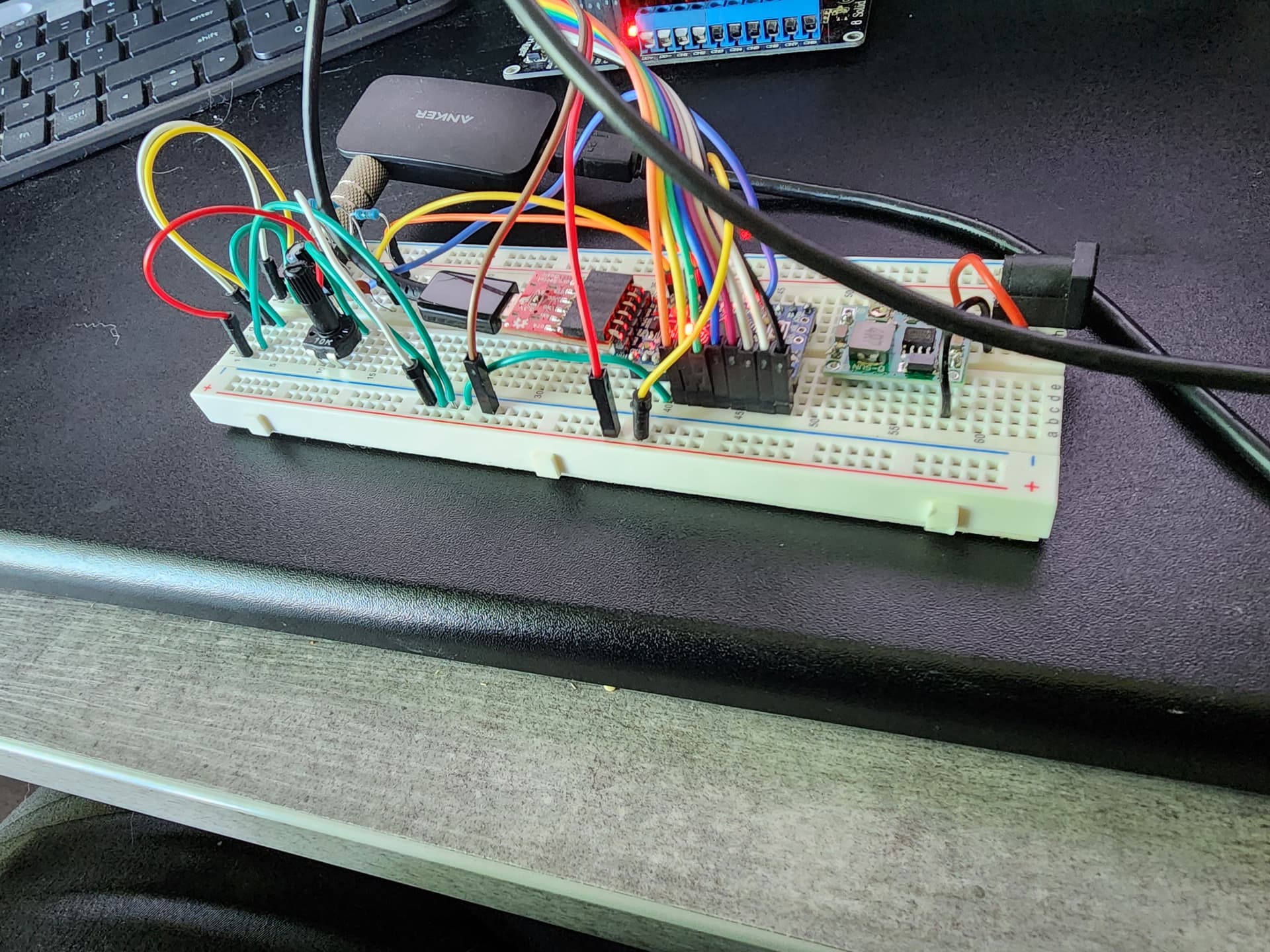
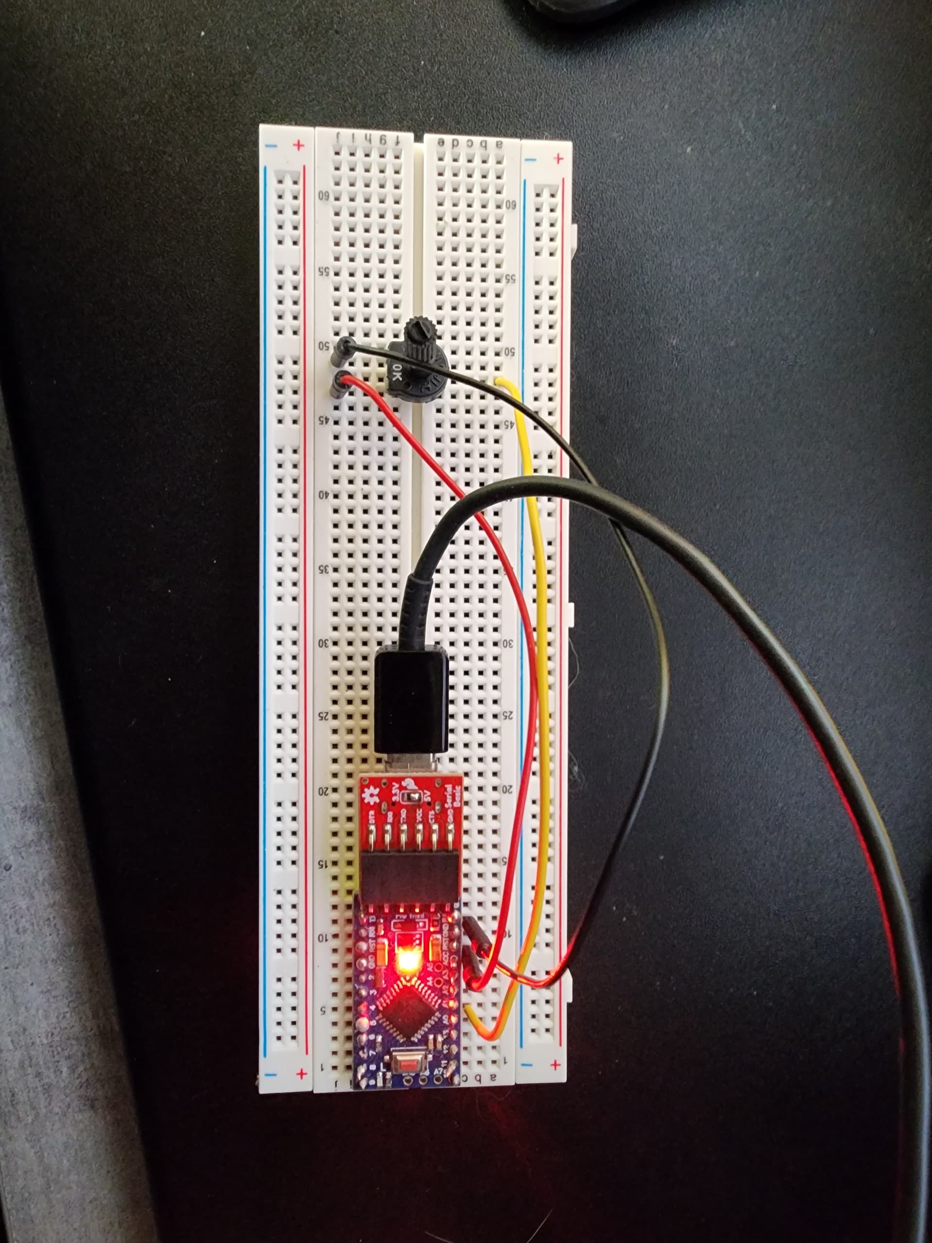
I am trying to build a Christmas light controller using this setup:
https://github.com/dimecoin/XmasFHT
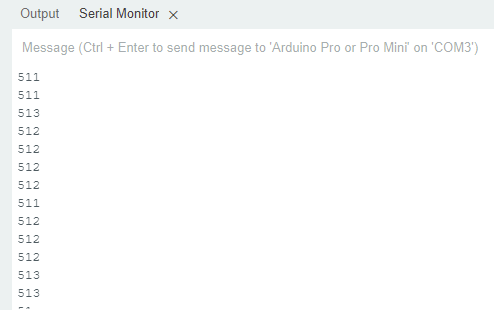
Everything is going well, but I am getting lots of noise on the circuit - nothing connected to the audio input, but getting readings on the serial monitor. Even with the "A0" wire disconnected from the Arduino, I still have data on the serial port.
How can I reduce the noise on the circuit?
Here's my serial monitor output:

This is the code I'm presently using:
/*
* Christmas Light Controller & Real Time Frequency Analyzer based on FHT code by Open Music Labs at http://openmusiclabs.com
*
* Then modified by PK from : https://dqydj.com/build-your-own-real-time-frequency-analyzer-and-christmas-light-controller/
*
* Modified by dimecoin: https://github.com/dimecoin/XmasFHT
*
* Requires FHT library, from here:
* 	http://wiki.openmusiclabs.com/wiki/ArduinoFHT
*/

/////////////////////////////////////////////////////////////////////
// Easy Customizations
/////////////////////////////////////////////////////////////////////

// Adjust the Treshold - what volume should make it light up?
#define THRESHOLD 35

// Old way if you want to statically set this.
// Attempt to 'zero out' noise when line in is 'quiet'.  You can change this to make some segments more sensitive.
// defaults:
// { 100, 81, 54, 47, 56, 58, 60, 67 };
//int oct_bias[] = { 136, 107, 44, 47, 56, 58, 60, 77 };

// New Auto calibration.
uint8_t oct_bias[] = { 0, 0, 0, 0, 0, 0, 0, 0 };
uint16_t cal_bias[] = { 0, 0, 0, 0, 0, 0, 0, 0 };

/* Number of times to sample the "natural noise" on wires to get average.
 * This average is used to cancel out noise while running.
 * Don't call to many times or will be slow to startup.
 * Dont' call over 16777215 or so times or it might overflow (plus would take forever to startup).
	ie. 256 (max reading) * CAL_TIME needs to be <= (2^32)-1 (size in bits of unint16_t)
*/

#define CAL_TIME 100

// Divide Threshold by 2 for top octave? 1 - yes 2 - no.  Makes highest frequency blink more.
#define TOP_OCTAVE_DIVIDE false

// This is for ACTIVE HIGH relays (works with LEDS for testing), switch values if you have ACTIVE LOW relays.
#define ACTIVE_ON LOW
#define ACTIVE_OFF HIGH

// enable for serial mode output, comment out to speed up lights
#define DEBUG

// Timer/delay for self test on startup.
#define SELFTESTTIME 100

/////////////////////////////////////////////////////////////////////
// Hard Customizations - know what you are doing, please.
/////////////////////////////////////////////////////////////////////
// FHT defaults - don't change without reading the Open Music Labs documentation at openmusiclabs.com
#define LOG_OUT 1		// use the log output function
#define FHT_N 256		// set to 256 point fht
#define OCTAVE 1
#define OCT_NORM 0

// include the library, must be done after some of the aboves are defined.. (required by FHT, won't work if included in wrong order)
#include <FHT.h>

// Delay - defines how many cycles before the lights will update.  OML's algorithm at 256 samples (needed for our 8 octaves) takes
// 3.18 ms per cycle, so we essentially throw out 14 cycles (I used mechanical relays, you can lower this for solid state relays).
// 15 cycles = 47.7 ms update rate.  Be careful here and don't change it too quickly!  I warned you!
// Default is 15
#define DELAY 15

// Don't change NUM_PINS.  FHT outputs 8 octs.
#define NUM_PINS 8
// Pin configuration, there is only 8 channels here.  Add duplicate entries if you don't have 8 lights, must be 8!
int relayPins[] = { 2, 3, 4, 5, 6, 7, 8, 9 };

uint8_t x[NUM_PINS];


void frequencyGraph(uint8_t x[], int size);

void setup() {

	// pin setup
	for (int i = 0; i < NUM_PINS; i++) {
		pinMode(relayPins[i], OUTPUT);
		digitalWrite(relayPins[i], ACTIVE_OFF);
	}

	// quick self test
	for (int i = 0; i < 2; i++) {
		for (int j = 0; j < NUM_PINS; j++) {
			digitalWrite(relayPins[j], ACTIVE_ON);
			delay(SELFTESTTIME);
			digitalWrite(relayPins[j], ACTIVE_OFF);
		}
	}

#ifdef DEBUG
	Serial.begin(115200);
	while (!Serial) {
	};
#endif

	TIMSK0 = 0;		// turn off timer0 for lower jitter
	ADCSRA = 0xe5;		// set the adc to free running mode

	// This is setting up A0 - dime
	ADMUX = 0x40;		// use adc0
	DIDR0 = 0x01;		// turn off the digital input for adc0

}

/**********************************************************************************
  Loop - includes initialization function and the full loop

**********************************************************************************/

void loop() {

	// True full loop
	int q = 0;
	int cal = 0;

	while (1) {		// reduces jitter

		cli();		// UDRE interrupt slows this way down on arduino1.0

		for (int i = 0; i < FHT_N; i++) {	// save 256 samples
			while (!(ADCSRA & 0x10)) ;	// wait for adc to be ready
			ADCSRA = 0xf5;	// restart adc

			// This is his way of reading Analog 0 (A0).  It pulls in L[ow] and H[igh] bit. - dimecoin
			byte m = ADCL;	// fetch adc data
			byte j = ADCH;

			int k = (j << 8) | m;	// form into an int
			k -= 0x0200;	// form into a signed int
			k <<= 6;	// form into a 16b signed int
			fht_input[i] = k;	// put real data into bins
		}

		fht_window();	// window the data for better frequency response
		fht_reorder();	// reorder the data before doing the fht
		fht_run();	// process the data in the fht
		fht_mag_octave();	// take the output of the fht

		sei();

		// We are in calibration mode.
		if (cal < CAL_TIME) {

			for (int i = 0; i < NUM_PINS; ++i) {
				cal_bias[i] += fht_oct_out[i];
			}

#ifdef DEBUG
			Serial.print(F("Calibrating "));
			Serial.print(cal);
			Serial.print(F("/"));
			Serial.println(CAL_TIME);
#endif

			cal++;
			continue;
		}
		// Calibration mode has just ended, crunch data collected.
		if (cal == CAL_TIME) {

			for (int i = 0; i < NUM_PINS; ++i) {
				oct_bias[i] = (uint8_t) (cal_bias[i] / CAL_TIME);
			}

#ifdef DEBUG
			Serial.println(F("--------------------------------------"));
			Serial.println(F("Done with Cal"));

			for (int i = 0; i < NUM_PINS; ++i) {
				Serial.print(oct_bias[i]);
				Serial.print(" ");
			}

			Serial.println(F(""));
			Serial.println(F("--------------------------------------"));

			for (int i = 0; i < NUM_PINS; ++i) {
				Serial.print(fht_oct_out[i] - oct_bias[i]);
				Serial.print(F(" "));
			}
			Serial.println(F(""));
			Serial.println(F("--------------------------------------"));

			Serial.flush();

#endif

			// Ready signal.
			for (int i = 0; i < NUM_PINS; i++) {
				digitalWrite(relayPins[i], ACTIVE_ON);
			}
			for (int i = 0; i < NUM_PINS; i++) {
				digitalWrite(relayPins[i], ACTIVE_OFF);
			}

			cal++;
			continue;
		}
		// Normal play mode

		if (q % DELAY == 0) {

			for (int i = 0; i < NUM_PINS; i++) {
				x[i] = fht_oct_out[i] - oct_bias[i];
			}

			frequencyGraph(x, NUM_PINS);

#ifdef DEBUG
			for (int i = 0; i < NUM_PINS; ++i) {
				Serial.print(x[i]);
				Serial.print(F(" "));
			}
			Serial.println(F(""));
#endif

		}

		++q;
	}

}

void frequencyGraph(uint8_t x[], int size) {

	int top_threshold = THRESHOLD;

	for (int i = 0; i < size - 1; i++) {
		x[i] = max(x[i], 0);

		// Special logic for last pin
		if (TOP_OCTAVE_DIVIDE && i == (size - 1)) {
			top_threshold /= 2;
		}

		if (x[i] >= top_threshold) {
			digitalWrite(relayPins[i], ACTIVE_ON);
		} else if (x[i] < top_threshold) {
			// && digitalRead(relayPins[i]) == ACTIVE_ON ) {
			digitalWrite(relayPins[i], ACTIVE_OFF);
		}

	}

}