@olikraus
Hello,
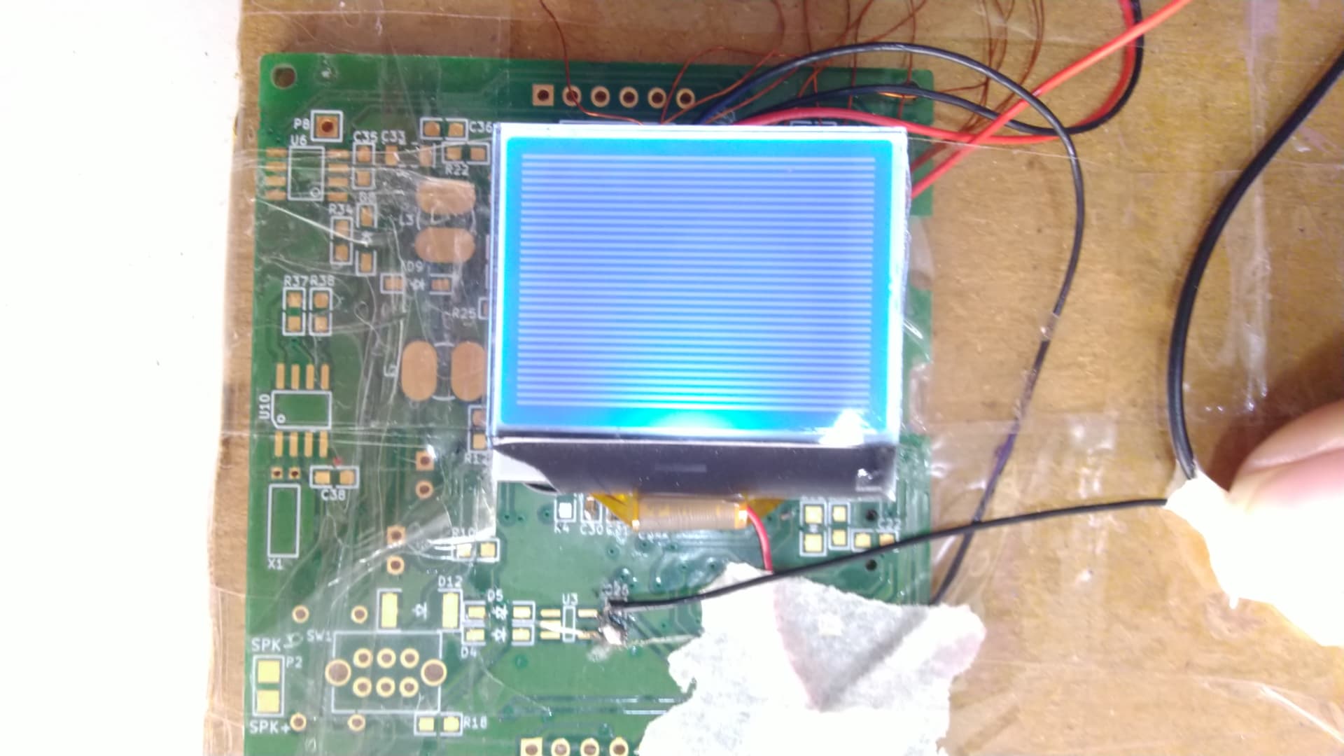
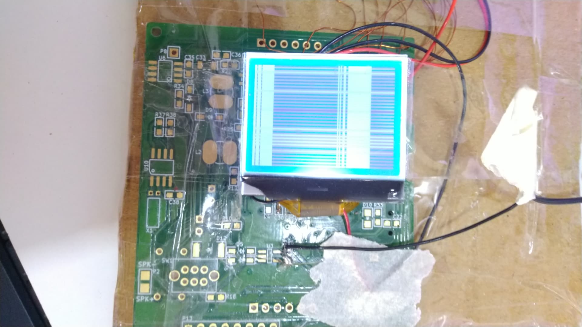
I used ST7567A driver LCD display as a 8 bit parallel mode interface with Arduino UNO
This is a pinout of ST7567A driver LCD
Datasheet
ST7567A_v1.2a.pdf (1.8 MB)
I used u8g2.h Library. in this library example full buffer --> graphic test I used.
/*

  GraphicsTest.ino

  Universal 8bit Graphics Library (https://github.com/olikraus/u8g2/)

  Copyright (c) 2016, olikraus@gmail.com
  All rights reserved.

  Redistribution and use in source and binary forms, with or without modification,
  are permitted provided that the following conditions are met:

  * Redistributions of source code must retain the above copyright notice, this list
    of conditions and the following disclaimer.

  * Redistributions in binary form must reproduce the above copyright notice, this
    list of conditions and the following disclaimer in the documentation and/or other
    materials provided with the distribution.

  THIS SOFTWARE IS PROVIDED BY THE COPYRIGHT HOLDERS AND
  CONTRIBUTORS "AS IS" AND ANY EXPRESS OR IMPLIED WARRANTIES,
  INCLUDING, BUT NOT LIMITED TO, THE IMPLIED WARRANTIES OF
  MERCHANTABILITY AND FITNESS FOR A PARTICULAR PURPOSE ARE
  DISCLAIMED. IN NO EVENT SHALL THE COPYRIGHT HOLDER OR
  CONTRIBUTORS BE LIABLE FOR ANY DIRECT, INDIRECT, INCIDENTAL,
  SPECIAL, EXEMPLARY, OR CONSEQUENTIAL DAMAGES (INCLUDING, BUT
  NOT LIMITED TO, PROCUREMENT OF SUBSTITUTE GOODS OR SERVICES;
  LOSS OF USE, DATA, OR PROFITS; OR BUSINESS INTERRUPTION) HOWEVER
  CAUSED AND ON ANY THEORY OF LIABILITY, WHETHER IN CONTRACT,
  STRICT LIABILITY, OR TORT (INCLUDING NEGLIGENCE OR OTHERWISE)
  ARISING IN ANY WAY OUT OF THE USE OF THIS SOFTWARE, EVEN IF
  ADVISED OF THE POSSIBILITY OF SUCH DAMAGE.

*/

#include <Arduino.h>
#include <U8g2lib.h>

#ifdef U8X8_HAVE_HW_SPI
#include <SPI.h>
#endif
#ifdef U8X8_HAVE_HW_I2C
#include <Wire.h>
#endif

/*
  U8g2lib Example Overview:
Frame Buffer Examples: clearBuffer/sendBuffer. Fast, but may not work with all Arduino boards because of RAM consumption
    Page Buffer Examples: firstPage/nextPage. Less RAM usage, should work with all Arduino boards.
   U8x8 Text Only Example: No RAM usage, direct communication with display controller. No graphics, 8x8 Text only.
*/

// Please UNCOMMENT one of the contructor lines below
// U8g2 Contructor List (Frame Buffer)
// The complete list is available here: https://github.com/olikraus/u8g2/wiki/u8g2setupcpp
// Please update the pin numbers according to your setup. Use U8X8_PIN_NONE if the reset pin is not connected


//U8G2_ST7567_PI_132X64_F_4W_SW_SPI u8g2(U8G2_R0, /* clock=*/ 13, /* data=*/ 11, /* cs=*/ 7, /* dc=*/ 9, /* reset=*/ 8); // Pax Instruments Shield, LCD_BL=6
//U8G2_ST7567_PI_132X64_F_4W_HW_SPI u8g2(U8G2_R0, /* cs=*/ 7, /* dc=*/ 9, /* reset=*/ 8);// Pax Instruments Shield, LCD_BL=6
//U8G2_ST7567_JLX12864_F_4W_SW_SPI u8g2(U8G2_R0, /* clock=*/ 13, /* data=*/ 11, /* cs=*/ 7, /* dc=*/ 9, /* reset=*/ 8);
//U8G2_ST7567_JLX12864_F_4W_HW_SPI u8g2(U8G2_R0, /* cs=*/ 7, /* dc=*/ 9, /* reset=*/ 8);
//U8G2_ST7567_122X32_F_4W_SW_SPI u8g2(U8G2_R0, /* clock=*/ 13, /* data=*/ 11, /* cs=*/ 7, /* dc=*/ 9, /* reset=*/ 8);
//U8G2_ST7567_122X32_F_4W_HW_SPI u8g2(U8G2_R0, /* cs=*/ 7, /* dc=*/ 9, /* reset=*/ 8);
//U8G2_ST7567_OS12864_F_4W_SW_SPI u8g2(U8G2_R0, /* clock=*/ 13, /* data=*/ 11, /* cs=*/ 7, /* dc=*/ 9, /* reset=*/ 8);
//U8G2_ST7567_OS12864_F_4W_HW_SPI u8g2(U8G2_R0, /* cs=*/ 7, /* dc=*/ 9, /* reset=*/ 8);
//U8G2_ST7567_ENH_DG128064_F_4W_SW_SPI u8g2(U8G2_R0, /* clock=*/ 13, /* data=*/ 11, /* cs=*/ 10, /* dc=*/ 9, /* reset=*/ 8);
//U8G2_ST7567_ENH_DG128064_F_4W_HW_SPI u8g2(U8G2_R0, /* cs=*/ 10, /* dc=*/ 9, /* reset=*/ 8);
//U8G2_ST7567_ENH_DG128064I_F_4W_SW_SPI u8g2(U8G2_R0, /* clock=*/ 13, /* data=*/ 11, /* cs=*/ 10, /* dc=*/ 9, /* reset=*/ 8);
//U8G2_ST7567_ENH_DG128064I_F_4W_HW_SPI u8g2(U8G2_R0, /* cs=*/ 10, /* dc=*/ 9, /* reset=*/ 8);
//U8G2_ST7567_64X32_F_HW_I2C u8g2(U8G2_R0, /* reset=*/ U8X8_PIN_NONE);
//U8G2_ST7567_HEM6432_F_HW_I2C u8g2(U8G2_R0, /* reset=*/ U8X8_PIN_NONE);
//U8G2_ST7567_ERC13232_F_4W_SW_SPI u8g2(U8G2_R0, /* clock=*/ 13, /* data=*/ 11, /* cs=*/ 10, /* dc=*/ 9, /* reset=*/ 8);
//U8G2_ST7567_ERC13232_F_4W_HW_SPI u8g2(U8G2_R0, /* cs=*/ 10, /* dc=*/ 9, /* reset=*/ 8);


U8G2_ST7567_OS12864_F_8080 u8g2(U8G2_R0, /* d0=*/9 , /* d1=*/8 , /* d2=*/7 , /* d3=*/6 , /* d4=*/5, /* d5=*/4 , /* d6=*/3 ,/* d7=*/ 2 , /*enable=*/ 10, /*cs=*/ 13, /*dc=*/ 11, /*reset =*/ 12);

void u8g2_prepare(void) {
  u8g2.setFont(u8g2_font_6x10_tf);
  u8g2.setFontRefHeightExtendedText();
  u8g2.setDrawColor(1);
  u8g2.setFontPosTop();
  u8g2.setFontDirection(0);
}

void u8g2_box_frame(uint8_t a) {
  u8g2.drawStr( 0, 0, "drawBox");
  u8g2.drawBox(5,10,20,10);
  u8g2.drawBox(10+a,15,30,7);
  u8g2.drawStr( 0, 30, "drawFrame");
  u8g2.drawFrame(5,10+30,20,10);
  u8g2.drawFrame(10+a,15+30,30,7);
}

void u8g2_disc_circle(uint8_t a) {
  u8g2.drawStr( 0, 0, "drawDisc");
  u8g2.drawDisc(10,18,9);
  u8g2.drawDisc(24+a,16,7);
  u8g2.drawStr( 0, 30, "drawCircle");
  u8g2.drawCircle(10,18+30,9);
  u8g2.drawCircle(24+a,16+30,7);
}

void u8g2_r_frame(uint8_t a) {
  u8g2.drawStr( 0, 0, "drawRFrame/Box");
  u8g2.drawRFrame(5, 10,40,30, a+1);
  u8g2.drawRBox(50, 10,25,40, a+1);
}

void u8g2_string(uint8_t a) {
  u8g2.setFontDirection(0);
  u8g2.drawStr(30+a,31, " 0");
  u8g2.setFontDirection(1);
  u8g2.drawStr(30,31+a, " 90");
  u8g2.setFontDirection(2);
  u8g2.drawStr(30-a,31, " 180");
  u8g2.setFontDirection(3);
  u8g2.drawStr(30,31-a, " 270");
}

void u8g2_line(uint8_t a) {
  u8g2.drawStr( 0, 0, "drawLine");
  u8g2.drawLine(7+a, 10, 40, 55);
  u8g2.drawLine(7+a*2, 10, 60, 55);
  u8g2.drawLine(7+a*3, 10, 80, 55);
  u8g2.drawLine(7+a*4, 10, 100, 55);
}

void u8g2_triangle(uint8_t a) {
  uint16_t offset = a;
  u8g2.drawStr( 0, 0, "drawTriangle");
  u8g2.drawTriangle(14,7, 45,30, 10,40);
  u8g2.drawTriangle(14+offset,7-offset, 45+offset,30-offset, 57+offset,10-offset);
  u8g2.drawTriangle(57+offset*2,10, 45+offset*2,30, 86+offset*2,53);
  u8g2.drawTriangle(10+offset,40+offset, 45+offset,30+offset, 86+offset,53+offset);
}

void u8g2_ascii_1() {
  char s[2] = " ";
  uint8_t x, y;
  u8g2.drawStr( 0, 0, "ASCII page 1");
  for( y = 0; y < 6; y++ ) {
    for( x = 0; x < 16; x++ ) {
      s[0] = y*16 + x + 32;
      u8g2.drawStr(x*7, y*10+10, s);
    }
  }
}

void u8g2_ascii_2() {
  char s[2] = " ";
  uint8_t x, y;
  u8g2.drawStr( 0, 0, "ASCII page 2");
  for( y = 0; y < 6; y++ ) {
    for( x = 0; x < 16; x++ ) {
      s[0] = y*16 + x + 160;
      u8g2.drawStr(x*7, y*10+10, s);
    }
  }
}

void u8g2_extra_page(uint8_t a)
{
  u8g2.drawStr( 0, 0, "Unicode");
  u8g2.setFont(u8g2_font_unifont_t_symbols);
  u8g2.setFontPosTop();
  u8g2.drawUTF8(0, 24, "☀ ☁");
  switch(a) {
    case 0:
    case 1:
    case 2:
    case 3:
      u8g2.drawUTF8(a*3, 36, "☂");
      break;
    case 4:
    case 5:
    case 6:
    case 7:
      u8g2.drawUTF8(a*3, 36, "☔");
      break;
  }
}

#define cross_width 24
#define cross_height 24
static const unsigned char cross_bits[] U8X8_PROGMEM = {
  0x00, 0x18, 0x00, 0x00, 0x24, 0x00, 0x00, 0x24, 0x00, 0x00, 0x42, 0x00,
  0x00, 0x42, 0x00, 0x00, 0x42, 0x00, 0x00, 0x81, 0x00, 0x00, 0x81, 0x00,
  0xC0, 0x00, 0x03, 0x38, 0x3C, 0x1C, 0x06, 0x42, 0x60, 0x01, 0x42, 0x80,
  0x01, 0x42, 0x80, 0x06, 0x42, 0x60, 0x38, 0x3C, 0x1C, 0xC0, 0x00, 0x03,
  0x00, 0x81, 0x00, 0x00, 0x81, 0x00, 0x00, 0x42, 0x00, 0x00, 0x42, 0x00,
  0x00, 0x42, 0x00, 0x00, 0x24, 0x00, 0x00, 0x24, 0x00, 0x00, 0x18, 0x00, };

#define cross_fill_width 24
#define cross_fill_height 24
static const unsigned char cross_fill_bits[] U8X8_PROGMEM = {
  0x00, 0x00, 0x00, 0x00, 0x00, 0x00, 0x18, 0x00, 0x18, 0x64, 0x00, 0x26,
  0x84, 0x00, 0x21, 0x08, 0x81, 0x10, 0x08, 0x42, 0x10, 0x10, 0x3C, 0x08,
  0x20, 0x00, 0x04, 0x40, 0x00, 0x02, 0x80, 0x00, 0x01, 0x80, 0x18, 0x01,
  0x80, 0x18, 0x01, 0x80, 0x00, 0x01, 0x40, 0x00, 0x02, 0x20, 0x00, 0x04,
  0x10, 0x3C, 0x08, 0x08, 0x42, 0x10, 0x08, 0x81, 0x10, 0x84, 0x00, 0x21,
  0x64, 0x00, 0x26, 0x18, 0x00, 0x18, 0x00, 0x00, 0x00, 0x00, 0x00, 0x00, };

#define cross_block_width 14
#define cross_block_height 14
static const unsigned char cross_block_bits[] U8X8_PROGMEM = {
  0xFF, 0x3F, 0x01, 0x20, 0x01, 0x20, 0x01, 0x20, 0x01, 0x20, 0x01, 0x20,
  0xC1, 0x20, 0xC1, 0x20, 0x01, 0x20, 0x01, 0x20, 0x01, 0x20, 0x01, 0x20,
  0x01, 0x20, 0xFF, 0x3F, };

void u8g2_bitmap_overlay(uint8_t a) {
  uint8_t frame_size = 28;

  u8g2.drawStr(0, 0, "Bitmap overlay");

  u8g2.drawStr(0, frame_size + 12, "Solid / transparent");
  u8g2.setBitmapMode(false /* solid */);
  u8g2.drawFrame(0, 10, frame_size, frame_size);
  u8g2.drawXBMP(2, 12, cross_width, cross_height, cross_bits);
  if(a & 4)
    u8g2.drawXBMP(7, 17, cross_block_width, cross_block_height, cross_block_bits);

  u8g2.setBitmapMode(true /* transparent*/);
  u8g2.drawFrame(frame_size + 5, 10, frame_size, frame_size);
  u8g2.drawXBMP(frame_size + 7, 12, cross_width, cross_height, cross_bits);
  if(a & 4)
    u8g2.drawXBMP(frame_size + 12, 17, cross_block_width, cross_block_height, cross_block_bits);
}

void u8g2_bitmap_modes(uint8_t transparent) {
  const uint8_t frame_size = 24;

  u8g2.drawBox(0, frame_size * 0.5, frame_size * 5, frame_size);
  u8g2.drawStr(frame_size * 0.5, 50, "Black");
  u8g2.drawStr(frame_size * 2, 50, "White");
  u8g2.drawStr(frame_size * 3.5, 50, "XOR");

  if(!transparent) {
    u8g2.setBitmapMode(false /* solid */);
    u8g2.drawStr(0, 0, "Solid bitmap");
  } else {
    u8g2.setBitmapMode(true /* transparent*/);
    u8g2.drawStr(0, 0, "Transparent bitmap");
  }
  u8g2.setDrawColor(0);// Black
  u8g2.drawXBMP(frame_size * 0.5, 24, cross_width, cross_height, cross_bits);
  u8g2.setDrawColor(1); // White
  u8g2.drawXBMP(frame_size * 2, 24, cross_width, cross_height, cross_bits);
  u8g2.setDrawColor(2); // XOR
  u8g2.drawXBMP(frame_size * 3.5, 24, cross_width, cross_height, cross_bits);
}

uint8_t draw_state = 0;

void draw(void) {
  u8g2_prepare();
  switch(draw_state >> 3) {
    case 0: u8g2_box_frame(draw_state&7); break;
    case 1: u8g2_disc_circle(draw_state&7); break;
    case 2: u8g2_r_frame(draw_state&7); break;
    case 3: u8g2_string(draw_state&7); break;
    case 4: u8g2_line(draw_state&7); break;
    case 5: u8g2_triangle(draw_state&7); break;
    case 6: u8g2_ascii_1(); break;
    case 7: u8g2_ascii_2(); break;
    case 8: u8g2_extra_page(draw_state&7); break;
    case 9: u8g2_bitmap_modes(0); break;
    case 10: u8g2_bitmap_modes(1); break;
    case 11: u8g2_bitmap_overlay(draw_state&7); break;
  }
}

void setup(void) {
  u8g2.begin();
u8g2.setContrast(180);

}

void loop(void) {
  // picture loop
  u8g2.clearBuffer();
  draw();
  u8g2.sendBuffer();

  // increase the state
  draw_state++;
  if ( draw_state >= 12*8 )
    draw_state = 0;

  // deley between each page
  delay(100);

}
I use this pin configuration
LCD pins    -->   Arduino UNO pins
D7          -->         2
D6          -->         3
D5          -->         4
D4          -->         5
D3          -->         6
D2          -->         7
D1          -->         8
D0          -->         9
ERD         -->        3.3v
RWR         -->         10
A0          -->         11
RSTB        -->         12
CSB         -->         13
This full information related my project all the documents, pin configuration datasheet etc..