Hello guys!
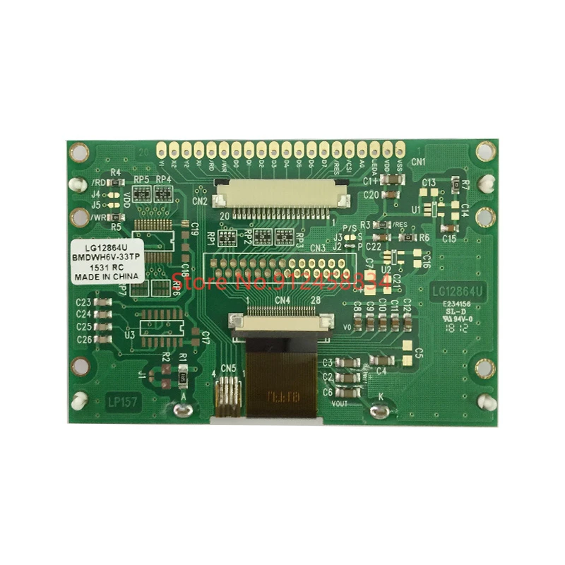
I bought an LCD display whose nameplate can be found here: https://www.lairui.com/uploads/file/2020614/LG12864K-DW.pdf !
The company sent a word document containing a drawing of the LCD connection! Based on the drawing, the connection panel (3.3V) is ready!


So far there is no problem (soldered, resistors connected in the right places), but they can't tell you which U8G2 should be used for it, apart from ST7565 !! Another thing is that nothing appears on the display (no light, no factory preset icon or anything else)! When connecting, only a few stripes appear vertically and horizontally, but they disappear after a maximum of 0.5 seconds!
Has anyone encountered this display or something similar?
Arduino Mega that I use !!
I have included another part that I think controls the settings of the lcd, for which #include <U8g2lib.h> indicates an error:
void LCD_Init(void)
{
	LCD_WriteCommand(0xAE);   // Set Display On/Off
	                          // Default => 0xAE
	                          // 0xAE => Display Off
	                          // 0xAF => Display On

	LCD_WriteCommand(0xA2);   // Set LCD Bias
	                          // Default => 0xA2
	                          // 0xA2 => 1/9 Bias
	                          // 0xA3 => 1/7 Bias

	if (DIRECTION == 1)          // Set NORMAL display direction
	                          // DIRECTION=1, SEG normal/COM reverse
	{
		LCD_WriteCommand(0xA0); // ADC Select (Set SEG output direction)
		                        // Default => 0xA0
		                        // 0xA0 => ADC=0, SEG output normal direction. Column Address 0 Mapped to SEG0
		                        // 0xA1 => ADC=1, SEG output reverse direction. Column Address 131 Mapped to SEG0
		LCD_WriteCommand(0xC8); // COM Output Mode Select (Set COM output scan direction)
		                        // Default => 0xC0
		                        // 0xC0 => COM output scan normal direction. Scan from COM0 to 63
		                        // 0xC8 => COM output scan reverse direction. Scan from COM63 to 0
	}
	else                       // Set REVERSE display direction
	                          // DIRECTION=0, SEG reverse/COM normal
	{
		LCD_WriteCommand(0xA1); // ADC Select (Set SEG output direction)
		                        // Default => 0xA0
		                        // 0xA0 => ADC=0, SEG output normal direction. Column Address 0 Mapped to SEG0
		                        // 0xA1 => ADC=1, SEG output reverse direction. Column Address 131 Mapped to SEG0
		LCD_WriteCommand(0xC0); // COM Output Mode Select (Set COM output scan direction)
		                        // Default => 0xC0
		                        // 0xC0 => COM output scan normal direction. Scan from COM0 to 63
		                        // 0xC8 => COM output scan reverse direction. Scan from COM63 to 0
	}

	LCD_WriteCommand(0xF8);   // Set Booster Ratio, users should set booster ratio to match hardware connection.
	LCD_WriteCommand(0x00);   // 0x00 => 2x,3x,4x
	                          // 0x01 => 5x
	                          // 0x11 => 6x
	LCD_WriteCommand(0x25);   // Set V0 Voltage Regulator Internal Resistor Ratio
	                          // Set 1+Rb/Ra=5.5 (D2D1D0=101)
	SetContrast(5);             // Set Contrast
	                          // IT IS STRONGLY SUGGESTED that users design the software with contrast adjustable

	LCD_WriteCommand(0x40);   // Set Start Line = 0
	LCD_WriteCommand(0x2C);   // Power Control Set
	                          // Set Booster Circuit (VC) ON
	LCD_WriteCommand(0x2E);   // Power Control Set
	                          // Set Booster Circuit (VC) & Voltage Regulator (VR) ON
	LCD_WriteCommand(0x2F);   // Power Control Set
	                          // Set Booster Circuit (VC) & Voltage Regulator (VR) & Voltage Follower (VF) ON
	ClearScreen();              // Clear screen before set display ON
	LCD_WriteCommand(0xAF);   // Set Display On/Off
	                          // Default => 0xAE
	                          // 0xAE => Display Off
	                          // 0xAF => Display On
}


//*******************************************************************
//  Set LCD contrast
//  contrastLevel: LCD contrast level, ranging from 0 to 10, total 11 levels.
//          	  0 = Minimum level
//                 5 = Medium level	(default)
//                10 = Maximum level
//
//  IT IS STRONGLY SUGGESTED that users design the software with contrast adjustable.
//
//*******************************************************************

void SetContrast(uchar contrastLevel)
{
	uchar contrast;                  //Electronic volume value

	contrast = 0x25 + 2*contrastLevel;   //Contrast for contrastLevel 5 = 0x25+2*5=0x2F
	                               //V0 = 10.3V
	LCD_WriteCommand(0x81);        //Electronic volume mode set
	LCD_WriteCommand(contrast);     //Set electronic volume value
}
SI = /* clock=/ 13
SCL = /* data=/ 11
A0 = /* dc=/ 9
CS1 =/ cs=*/ 10
For HW_SPI controllers, stripes appear on the display!
SW_SPI the display is completely empty!
The display receives 3.3V via 7803 mosfet!
I have already tried these from ST7565!
  U8G2_ST7567_OS12864_1_4W_SW_SPI u8g2(U8G2_R0, /* clock=*/ 13, /* data=*/ 11, /* cs=*/ 10, /* dc=*/ 9, /* reset=*/ A3);
  //U8G2_ST7567_JLX12864_1_4W_HW_SPI u8g2(U8G2_R0, /* cs=*/ 10, /* dc=*/ 9, /* reset=*/ A3);
  //U8G2_ST7567_OS12864_1_4W_HW_SPI u8g2(U8G2_R0, /* cs=*/ 10, /* dc=*/ 9, /* reset=*/ A3);
  //U8G2_ST7567_ENH_DG128064_1_4W_SW_SPI u8g2(U8G2_R0, /* clock=*/ 13, /* data=*/ 11, /* cs=*/ 10, /* dc=*/ 9, /* reset=*/ A3);
  //U8G2_ST7567_ENH_DG128064_1_4W_HW_SPI u8g2(U8G2_R0, /* cs=*/ 10, /* dc=*/9, /* reset=*/ A3);
  //U8G2_ST7567_ENH_DG128064I_1_4W_SW_SPI u8g2(U8G2_R0, /* clock=*/ 13, /* data=*/ 11, /* cs=*/ 10, /* dc=*/ 9, /* reset=*/ A3);
  //U8G2_ST7567_ENH_DG128064I_1_4W_HW_SPI u8g2(U8G2_R0, /* cs=*/ 13, /* dc=*/ 9, /* reset=*/ A3);
  // U8G2_ST7565_64128N_F_4W_HW_SPI u8g2(U8G2_R0, /* cs=*/ 13, /* dc=*/ 9, /* reset=*/ A3);

  // U8G2_ST7565_LM6059_1_4W_HW_SPI u8g2(U8G2_R0, /* cs=*/ 10, /* dc=*/ 9, /* reset=*/ A3);
  // U8G2_ST7565_64128N_1_4W_SW_SPI u8g2(U8G2_R0, /* clock=*/ 13, /* data=*/ 11, /* cs=*/ 10, /* dc=*/ 9, /* reset=*/ A3);
  //  U8G2_ST7565_LM6059_1_4W_HW_SPI u8g2(U8G2_R0, /* cs=*/ 10, /* dc=*/ 9, /* reset=*/ A3);
  //  U8G2_ST7565_ERC12864_F_4W_HW_SPI u8g2(U8G2_R0, /* cs=*/ 10, /* dc=*/ 9, /* reset=*/ A3);
  //  U8G2_ST7565_ERC12864_ALT_F_4W_HW_SPI u8g2(U8G2_R0, /* cs=*/ 10, /* dc=*/ 9, /* reset=*/ A3);
  // U8G2_ST7565_64128N_F_4W_SW_SPI u8g2(U8G2_R0, /* clock=*/ 13, /* data=*/ 11, /* cs=*/ 10, /* dc=*/ 9, /* reset=*/ A3);


  // U8G2_ST7565_EA_DOGM128_1_4W_SW_SPI u8g2(U8G2_R0, /* clock=*/ 13, /* data=*/ 11, /* cs=*/ 10, /* dc=*/ 9, /* reset=*/ A3);
  //  U8G2_ST7565_EA_DOGM128_1_4W_HW_SPI u8g2(U8G2_R0, /* cs=*/ 10, /* dc=*/ 9, /* reset=*/ A3);
  //U8G2_ST7565_64128N_1_4W_SW_SPI u8g2(U8G2_R0, /* clock=*/ 13, /* data=*/ 11, /* cs=*/ 10, /* dc=*/ 9, /* reset=*/ A3);
  //  U8G2_ST7565_64128N_1_4W_HW_SPI u8g2(U8G2_R0, /* cs=*/ 10, /* dc=*/ 9, /* reset=*/ A3);
  //U8G2_ST7565_EA_DOGM132_1_4W_SW_SPI u8g2(U8G2_R0, /* clock=*/ 13, /* data=*/ 11, /* cs=*/ 10, /* dc=*/ 9, /* reset=*/ U8X8_PIN_NONE);	// DOGM132 Shield
  //  U8G2_ST7565_EA_DOGM132_1_4W_HW_SPI u8g2(U8G2_R0, /* cs=*/ 13, /* dc=*/ 11, /* reset=*/ U8X8_PIN_NONE);	// DOGM132 Shield
  //U8G2_ST7565_ZOLEN_128X64_1_4W_SW_SPI u8g2(U8G2_R0, /* clock=*/ 13, /* data=*/ 11, /* cs=*/ 10, /* dc=*/ 9, /* reset=*/ A3);
  //  U8G2_ST7565_ZOLEN_128X64_1_4W_HW_SPI u8g2(U8G2_R0, /* cs=*/ 10, /* dc=*/ 9, /* reset=*/ A3);
  //U8G2_ST7565_LM6059_1_4W_SW_SPI u8g2(U8G2_R0, /* clock=*/ 13, /* data=*/ 11, /* cs=*/ 10, /* dc=*/ 9, /* reset=*/ A3);		// Adafruit ST7565 GLCD
  //  U8G2_ST7565_LM6059_1_4W_HW_SPI u8g2(U8G2_R0, /* cs=*/ 10, /* dc=*/ 9, /* reset=*/ A3);			// Adafruit ST7565 GLCD
  //U8G2_ST7565_KS0713_1_4W_SW_SPI u8g2(U8G2_R0, /* clock=*/ 13, /* data=*/ 11, /* cs=*/ 10, /* dc=*/ 9, /* reset=*/ A3);		// KS0713 controller
  //  U8G2_ST7565_KS0713_1_4W_HW_SPI u8g2(U8G2_R0, /* cs=*/ 10, /* dc=*/ 9, /* reset=*/ A3);			// KS0713 controller
  //U8G2_ST7565_LX12864_1_4W_SW_SPI u8g2(U8G2_R0, /* clock=*/ 13, /* data=*/ 11, /* cs=*/ 10, /* dc=*/ 9, /* reset=*/ A3);;
  //  U8G2_ST7565_LX12864_1_4W_HW_SPI u8g2(U8G2_R0, /* cs=*/ 10, /* dc=*/ 9, /* reset=*/ A3);
  //U8G2_ST7565_ERC12864_1_4W_SW_SPI u8g2(U8G2_R0, /* clock=*/ 13, /* data=*/ 11, /* cs=*/ 10, /* dc=*/ 9, /* reset=*/ A3);
  //  U8G2_ST7565_ERC12864_1_4W_HW_SPI u8g2(U8G2_R0, /* cs=*/ 10, /* dc=*/ 9, /* reset=*/ A3);
  //U8G2_ST7565_ERC12864_ALT_1_4W_SW_SPI u8g2(U8G2_R0, /* clock=*/ 13, /* data=*/ 11, /* cs=*/ 10, /* dc=*/ 9, /* reset=*/ A3); // contrast improved version for ERC12864
  //  U8G2_ST7565_ERC12864_ALT_1_4W_HW_SPI u8g2(U8G2_R0, /* cs=*/ 10, /* dc=*/ 9, /* reset=*/ A3); // contrast improved version for ERC12864
  //U8G2_ST7565_NHD_C12832_1_4W_SW_SPI u8g2(U8G2_R0, /* clock=*/ 13, /* data=*/ 11, /* cs=*/ 10, /* dc=*/ 22, /* reset=*/ A3);
  //  U8G2_ST7565_NHD_C12832_1_4W_HW_SPI u8g2(U8G2_R0, /* cs=*/ 10, /* dc=*/ 9, /* reset=*/ A3);
  //U8G2_ST7565_NHD_C12864_1_4W_SW_SPI u8g2(U8G2_R0, /* clock=*/ 13, /* data=*/ 11, /* cs=*/ 10, /* dc=*/ 9, /* reset=*/ A3);
  //  U8G2_ST7565_NHD_C12864_1_4W_HW_SPI u8g2(U8G2_R0, /* cs=*/ 10, /* dc=*/ 9, /* reset=*/ A3);
  //U8G2_ST7565_JLX12864_1_4W_SW_SPI u8g2(U8G2_R0, /* clock=*/ 13, /* data=*/ 11, /* cs=*/ 10, /* dc=*/ 9, /* reset=*/ A3);
  //  U8G2_ST7565_JLX12864_1_4W_HW_SPI u8g2(U8G2_R0, /* cs=*/ 10, /* dc=*/ 9, /* reset=*/ A3);


