Stepper motor 101

Hello,
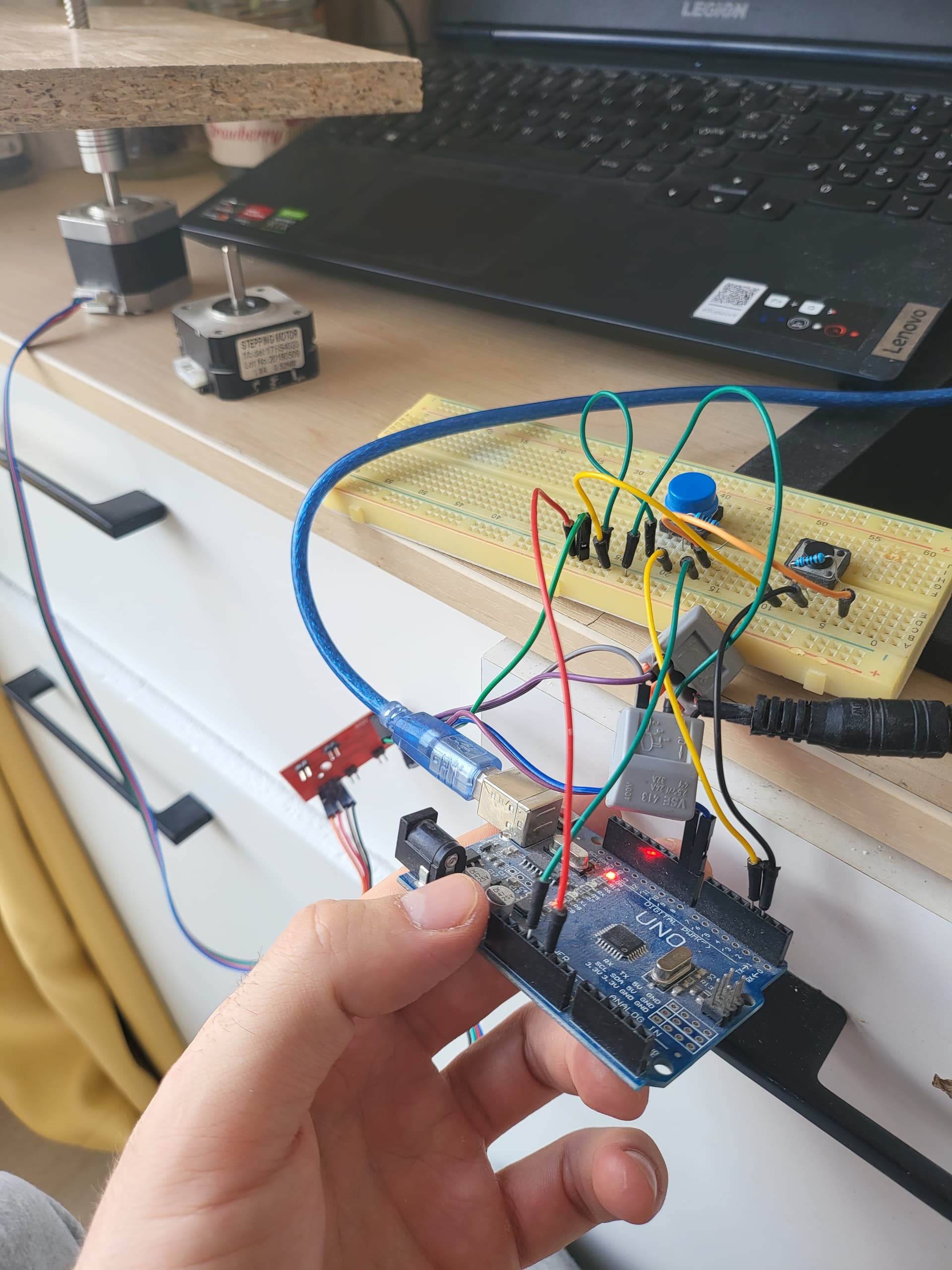
maybe anyone know why motor is only vibrating not turning.
Connected everything like in the post 1.6 version with two buttons

Easy Driver Examples (schmalzhaus.com)

#define DISTANCE 3200

int StepCounter = 0;
int Stepping = false;

void setup() {
  pinMode(8, OUTPUT);
  pinMode(9, OUTPUT);
  digitalWrite(8, LOW);
  digitalWrite(9, LOW);

  pinMode(2, INPUT);
  pinMode(3, INPUT);
}

void loop() {
  if (digitalRead(3) == LOW && Stepping == false)
  {
    digitalWrite(8, LOW);
    Stepping = true;
  }
  if (digitalRead(2) == LOW && Stepping == false)
  {
    digitalWrite(8, HIGH);
    Stepping = true;
  }

  if (Stepping == true)
  {
    digitalWrite(9, HIGH);
    delay(1);
    digitalWrite(9, LOW);
    delay(1);

    StepCounter = StepCounter + 1;

    if (StepCounter == DISTANCE)
    {
      StepCounter = 0;
      Stepping = false;
    }
  }
}

What is the stepper power supply?

Try increasing those delays to a higher number, say 100.

How are those switches wired? Do they have pullup or pulldown resistors?

Robin2's stepper basics.

Robin2's simple stepper code.

Power supply 2a and 12v. I tried putting delay to 100, but it stops vibrating makes old dsl router noises instead. Resistors from button to 2 and 3 inputs like in diagram


Did you adjust the current at the easydriver correctly ( the tiny pot ).

Did you Ohm out the motor or have a data sheet so that you know the stepper coil wiring arrangement?

image

Test without any load on the motor. Test with the other motor you have in the picture.

I tried with both of them

Yeah, tried it just now. If i put it to min volt then still vibrates if i max it, then it stops vibrating

I tried connecting in couple of ways stil lresult is the same, anyone has any ideas?


Anyone?

?any one

Check this video:

Do a similar test, just to be sure you get all the wires correct. You will also see if your motor is ok. You should get it stepping, one step at a time, as you switch how you feed power to the wires.

If everything works fine, you might spot an error you have done in connecting your stepper driver, an error not visible in everything you have shown us.
If you don't spot any error, you have to suspect your stepper driver. Make a program, where the stepper motor runs very slowly, say 3 seconds at each step. You will have time to measure the voltage over the motor A pair of wires, and over the B pair as well. Is there enough voltage? If not, your stepper driver is faulty. Or the amps running to the motor have burnt the contact surfaces in your solderless breadboard! If your multimeter can measure several amps, try to measure how many amps run through one wire to your stepper motor, using the same 3 s per step program. If very little, you probably keep burning the contact surfaces more and more. Better to solder the motor wires to the driver.

So, if you have only one bad contact of the four motor wires, one coil is constantly off. That makes the other coil turn the motor back and forth, when it should produce a constant rotation. A bipolar stepper motor is always in one of four stages. 1, 2, 3 or 4. To go 1, 2, 3, 4, 1, 2, 3, 4, 1, 2 etc, you activate the motor by A+, B+, A-, B-, A+, B+ etc. When one coil is off, it goes like A+, A-, A+, A-. But there's no defined way for the motor to react to that. It kind of jumps from 1 to 3 and back to 1, but it could do that clockwise or counterclockwise at each step, chaotically. In reality, the motor probably just jumps back and forth.

This topic was automatically closed 180 days after the last reply. New replies are no longer allowed.