I have a 11 switches who are one side connected to 5 Volt. The other side goes to pin 22-33 on the GiGa board. I want to flip the switch and in one perticullair order a L298 activates and is opening a lock. When all the switches are off again, a 12 th switch is lockling it up again by changing the polarity with the L298.
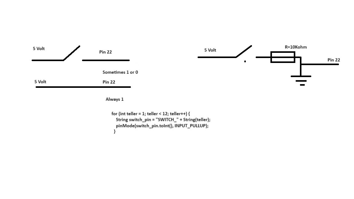
The problem is that when i read the pin, it is in on position always 1 and in the off position sometimes 1 and sometimes 0. So it is not 0 as i want it to be. I have programmed a INPUT_PULLUP, but that is not enough. Randomly 0 and 1 and then the program is not working. How can i make the hardware be always 0 when the switches are off and 1 when its on.
Welcome to the forum
You need to keep the switch pins in a known state at all times rather than having them floating at an unknown voltage, perhaps HIGH, perhaps LOW, perhaps changing
To do this you connect the pin to either GND or Vcc via a resistor to keep it HIGH or LOW then wire the switch to take the pin to the other state when the switch is closed
The easiest way to do this is to use INPUT_PULLUP in pinMode() to turn on the built in pullup resistor then to wire the switch to connect the pin to GND when closed
You can then detect HIGH as open and LOW as closed and take appropriate action
No. The resistor should go from the pin to GND (this is why it's called "pull-down").
But @UKHeliBob already suggested you a better and simpler solution, using INPUT_PULLUP.
Use it.
You've wired the switch directly to ground. It will read LOW no matter what.
resistor - between 5 volts and the input pin.
switch - between input pin and ground
reading: HIGH if the switch is open, not pressed
reading: LOW if the switch is closed, pressed.
a7
Thanks, it works
What works exactly ?
Have you used the internal pullup resistors, external pullup resistors or external pulldown resistors and have you changed the code in any way ?
I have used external 10K resistors against ground. On the connector before the resistors i connected the wire coming from pijn 22-33. And the pullup internal to 5 volt. So now it's measuring 0 when the switch is off and 1 when it's on. Always. Thanks for your support.
Robert
Is there a reason why you decided to use external resistors rather than the internal pullup resistors ?
- Remove all your switch resistors
- Connect your switches between GND and pins 22-33 as desired.
- Configure pins 22-33 as INPUT_PULLUP (pinMode(PIN#, INPUT_PULLUP)
- Read switches with digitalRead(PIN#) and they will read LOW when on and HIGH when off

I saw that schema before, and I still wonder why S1+R4 circuit is not recommended.
Given that I almost always use the internal pullup so I agree the INPUT_PULLUP is the best and simpler solution, but except for bad wiring or faulty cables I can't see how that external pull-down could risk a short circuit between +5V and GND.
1 Like
We are talking about a GiGa board. This board has internal pulldown resistors. So no need to change anything in the hardware wiring. Simply:
pinMode(buttonPin, INPUT_PULLDOWN);
+1 If it's already wired that way, there is no need to change it. When beginning from scratch, the internal pullup is definitely more easy.
WHAT???
I don't know if you mean what I can get from that, but if you use external pulldown there's no need for the internal one. Just keep the pinMode to just INPUT, don't use INPUT_PULLUP.
Or, even better, use INPUT_PULLUP and remove the external resistor (and remember the logic is reversed, LOW means "pressed")..
I think it's mainly a historical artifact of preference. Open collector outputs on sensors are common, and so in earlier microcontrollers, an internal pullup was added to make interfacing to them easier.
Newer microcontrollers (remember that the Mega328 used in classic Arduino is ancient!) have user selectable pullups or pulldowns.
And older digital logic parts, including microprocessors perhaps, had neither. So yeah history.
Which is why I am yet in the habit of using real resistors.
The internal pullup is nice, but it is a bit on the weak side, and there are circumstances where a stronger pull is desirable.
The real crime (!) is using a pull down so the switches read HIGH when pressed. It's so easy to code around that, same same with however one wires a LED.
a7
1 Like
Agree, and that picture should be updated to avoid false warnings.
Not really a crime, but if a newbie gets confused by that, he/she should just need kinda:
#define PRESSED LOW
#define RELEASED HIGH
...
  if (digitalRead(BUTTON) == PRESSED) {
    ..
  }
It was explained to me like this.
Often, switches are mounted on an outside panel of the casing, with wires trailing back to a circuit board mounted inside the casing. Those trailing wires can work loose or break or get trapped between a panel and the case body and damaged that way.
If one of those wires is 5V, and it breaks loose and touches something inside the case, there is likely to be a short circuit which could damage components.
But if that wire comes from 5V via a resistor (internal to the MCU or external on the circuit board) then if that wire comes loose and touches other components, there might be a malfunction, but the resistor will limit the current and to no permanent damage will be done.
Of course, if a wire which is directly connected to ground comes loose and touches other components, that could also cause a short circuit. But perhaps that's less likely for some reason, I'm not sure.
Yeah, I understand and it's the same explanation someone gave me some time ago. But IMHO it's more a matter of "philosophy" than something to do with practical engineering/wirings.
Just to make an example, cosider light bulbs and switches in our house. If the mains has a "live" and a "neutral" wire, it is best practice bringing the "neutral" up to the ceiling light bulb, and "live" to the switch: even if doing the reverse will give the same result (e.g. the lamp will turn on when the switch is activated), it is safer not constantly have live mains energy up to the bulb for safety reasons.
But in the Arduino environment, there aren't safety reasons (except for the power source and/or MCU itself if a short circuit comes out) so if I use either a pullup or a pulldown method doesn't make any difference, provided you keep +5V and GND wires far enough, properly connected, and without any kinda damage to them.
Assuming the case is grounded, and bringing a +5V cable to a switch on a metallic panel could cause a short circuit if the 5V cable is pinched and damaged and the touches the case, it is a unlikely sequence of events...
It looks to me like saying we shouldn't drive any internal combustion car because if the gas pump is defective or hardly hit with a hammer, or a pipe is not properly fixed, the gas could leak out and let the car explode. Yeah, no doubt about it. ![]()
It does however unlikely in the first place serve to further reduce opportunities for trouble.
So if all other things were ever equal, the preference would be to not route five volts when there would be no need to do.
I imagine that things like spacecraft and military electronics and nuclear power control systems have many inches of details specifications backed by at least as many pages of analysis around such seemingly unimportant matters.
I hope.
a7
1 Like