Hi,
i would like to switch between 2 batteries using n channel mosfets. i was thinking of connecting the pluses from both batteries and interrupting the negative of each battery.
is this possible?
Hi,
i would like to switch between 2 batteries using n channel mosfets. i was thinking of connecting the pluses from both batteries and interrupting the negative of each battery.
is this possible?
Use P channel MOSFETs.
You are suggesting high-side switching rather than low? is it completely impossible with n channel mosfets?
No it is relative easy you just need a voltage about 7 volts higher then the voltage you are switching for the gate. MOSFETs do not care as long as you satisfy the Vgs voltage. High side is recommended as you switch the gate to ground to turn it on and pull it up to VCC to turn off.
I think that should work with N-channel mosfets. Or you could do the same on the high side with P-channel mosfets.
Can you explain why you need to do this?
Usual approach is common ground and switch between batteries using P channet mosfets as high side switching. (as pointed out in # 2 above)
Do you might provide a schematic?
A picture is always worth a thousand words.
I agree, a schematic would help. I can think of problems with this, but until I see a schematic I can't be sure. People forget that when switching a battery the polarities are reversed because you are switching the source of power not the load. They also forget that when the circuit is 'off' there is no power available to control the switching device. However, these problems are speculation without seeing a proposed schematic.
This is the schematic i have now, it works but only when the 2 mosfet's drain isn't connected with each other. as soon as i connect it the other mosfet turns on even when its not supposed to. is there a way to fix this? I'm possibly switching around 134v so i need a solution which the mosfets can do it and wont blow up. I'm using ones which can support 200v.
im hoping to have a device which i can plug in lithium ion batteries and switch between them when one of them gets low without ever putting them in parallel with each other. for my electric bike.
ah i see, thanks for that. however I'm not sure how i can do this because if i have theoretically 134v the mosfet wont like that on its gate I'm sure. how can this be possible? also do you suggest a mosfet driver for this circuit? i have a lot i can put into but i just get confused with one mosfet driver saying high side and low side switching both of them. I'm not sure how i can add this to the circuit and it being able to work with my voltage requirement.
Thank you for the schematic but missing is anything about where the 5V comes from for the opto-couplers, and what the output supplies.
the supply for the optocoupler and arduino comes from a buck converter that's on one of the batteries.
sorry if my schematic wasn't clear its my third time making one. but the output is where i would plug into my load so the 2 inputs is where both batteries get connected and the output is the plus and minus of one of the 2 batteries.
if you suggest i use a mosfet driver, which i looked online has a high side driver and a low side driver in the same package, but I'm not sure if its possible to use in my circuit. or the way I'm doing it is possible and I'm missing something small.
Can you please update your schematic to show the 5V supply? The language of electronics is the schematic, not words.
Thank you
OK, so thank you for the improved schematic, however it is still incomplete. Where do GPIO1 and GPIO2 come from and what powers that device?
Please post a complete schematic including everything plus everything else, whether I or anyone else asked for it.
And what voltage are these batteries?
Thank you.
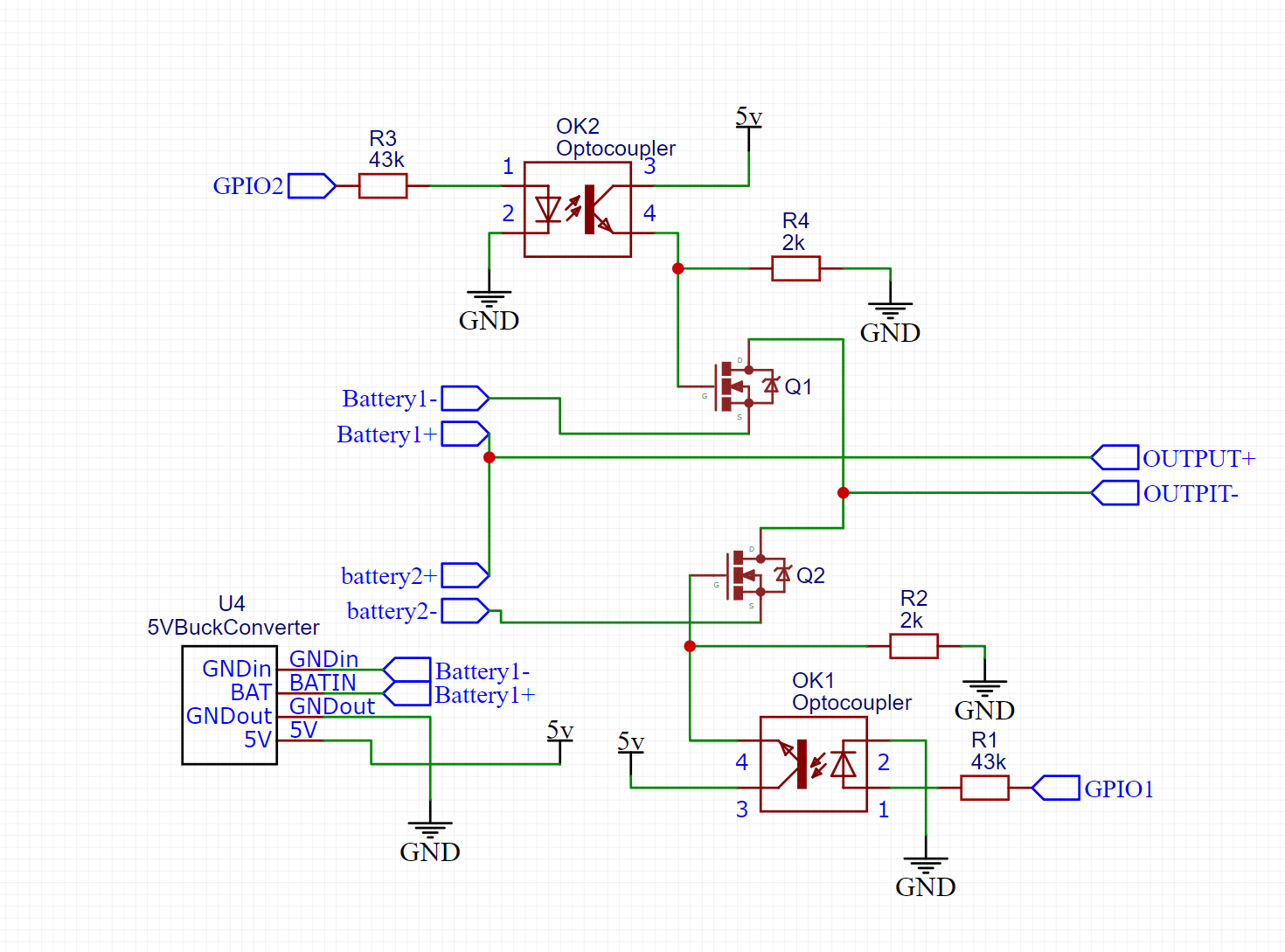
i think this should be everything. that is a connector which connects to the Arduino and power and 5v is taken from this circuit to power it.
I'm testing with 2 batteries both of which are 36v. but i would like to be able to switch batteries which will be 134v each.
this circuit works as intended only when the 2 drains of the mosfets aren't connected. it works perfectly but as soon as they are connected it all goes wrong ![]()
On most Arduinos GPIO1 is TxD for the serial port, so using it for anything else is asking for trouble.
Battery 1 -ve is connected to the control circuit via the buck converter, which completes the circuit from +5V, OK2, Q1 gate, Q1 source.
Battery 2 -ve is not in any way connected to the control circuit so there is no path back to ground for the control signal to Q2 gate.
Your circuit cannot work like this as you are of necessity separating the 2 negative terminals of the 2 batteries, but both need to be connected to the control circuit ground, which is in contradiction to the requirement for them the be separated.
The solution would be for the output side of each opto-coupler to be fed from the battery it controls, or to use a high side switch.
You might find this helpful: Common ground and why you need one
thank you very much for the detailed response, after thinking about your solution, if i use another buck converter that is connected to the other battery and give the output voltage to its optocoupler will that solve the issue?