You are trying to switch the -ve side of the batteries while at the same time have them at the same voltage as the controller ground, these are impossible conditions. Either they are connected together or they are not, you have to decide which and work with that. The more I think about it you cannot use a single buck converter from one battery like that because you are implicitly tying the -ve of one battery to the negative of the other, which you don't want.
Maybe someone else can suggest a way to achieve a low side switch, but at the moment, if you want to power your control circuit from either or both batteries then all the -ve terminals have to be tied together, which implies a high side switch.
Something to explore would be a buck converter that isolates the output from the input. I wanted just that to get 5VDC from 50VDC. I tried a mains 'wall wort', feeding it with 50VDC and found that it worked perfectly. I suggest that might work for you. What have you to lose by trying? Wall worts are free if you collect them from old electronics.
With the circuit given, it appears that a software problem could result is the two lithium ion batteries being connected together. If that could happen, its not normally a good idea, especially with large eBike type batteries.
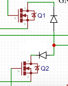
I'm not sure why the circuit doesn't work, but I suspect it may involve the body diodes of the mosfets. As a test, you might try adding diodes ahead of the drains to see if it works then:
I also wonder about GND, which is really Battery1- because they are connected in the buck converter.
I also wonder about finding a buck converter that works with 134V input.
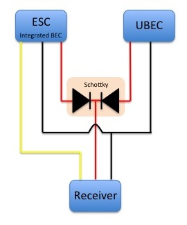
I really don't know how to make this work, even switching the high side. I guess I would consider putting the batteries in parallel, perhaps with diodes. But I assume we're looking at a lot of current here, so I don't know.
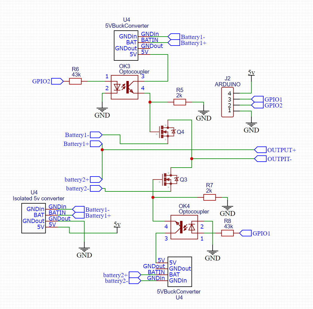
i have this isolated converter which i can use to power the logic and have 2 non-isolated converters on each of the optocouplers, i have made a schematic for you to have a look at.
Yep i have already taken that into account with bmses that detect if a large current flow is taking place/ fuses dotted around the place outside of this circuit. and the code will be written in a way that it will never be able to switch on both transistors at the same time.
i have buck converters which i have modified to take that voltage and lower it. also i have tried the diode method on the drain and it will get extremely hot while under load so id rather avoid that.
But do the diodes make the switching work? If they do, it might be possible to use two mosfets in series, with their drains connected, and their gates driven in common. That should get rid of the heat.
I don't believe that buck converter has isolation between input and output because it doesn't appear to use a transformer. Please check with an Ohm meter that there is open circuit between the input and the output connections.
I'm busy with something else at the moment, but a quick look at your schematic shows no complete circuit for the gate signal to the MOSFETS.
Here is a link to give you an idea, I do not think it is high enough voltage but there are other devices that go up to 100V or more and are opto isolated. You can look at this and other solid state relays, be sure they are for DC.
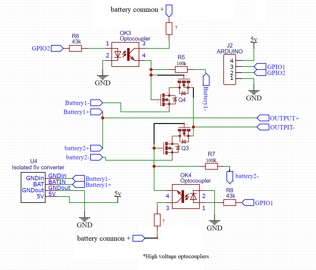
This is the best I could do to get the drains referenced workably. It would require optocouplers with high CE ratings. The 4N38 I believe is 80V. And the dual mosfets should switch completely with almost no voltage drop, so no heat. but I think something much simpler on the high side would be better, like a mechanical switch.
thank you for this circuit, however, im confused why have you put battery common + on the mosfet's gate? they are only switching battery - and if the gate voltage goes above 20v it may damage the mosfet right? or I'm missing something here.
The combination of the "?" resistor in the collector line and R5 would make a resistor divider that would drop what the gate sees to something lower than its maximum. So for example at 36V a 220K for the ? resistor and 100K for R5 would give you a gate voltage of 11.25V, which should work fine if the gate is rated at 20V. But you would also have to use an optocoupler that will withstand 36V C/E.
If you go to 134V, everything would have to be recalculated, and you would need different optocouplers and possibly different mosfets.
I should say that I wouldn't do it this way myself, but was just trying to get your circuit to work as well as possible. And I can't guarantee it will work. Perry or some other guru would have to rule on that. I was just trying to isolate the 5V stuff from the 36V stuff by way of the optocouplers. If it was me, I think I would put the batteries in parallel, and not bother with all this. But I know some consider that not to be a good idea.
Ah okay, thanks for that explanation. i did make your citcuit, and it is functional but i given the optocopulers 12v and its working but if i put a difference of 21 volts in between the batteries the mosfets start to get super hot. and had several break already the 2 batteries i was switching had 33v in one and 54v in the other. im just trying to figure out why it would make the mosfets hot..
Which mosfets are you using? And how much load current is involved in your test?
Mosfets get warm because of internal resistance, either because their RDSon spec is high, or because they aren't fully turned on. The key measurement would be the gate voltage when they are supposed to be on. A normal mosfet woulf probably need 10V on the gate to be fully on, but that depends on the mosfet.