im using irfb4110, load is nothing im just measuring with voltmeter and the arduino is switching the batteries every 3 seconds. optocopulers are tlp785.
Those parts look fine. If there's no load current, there should be no heat.
Yep that’s why I’m stumped. With both 35v battery and 33v battery it’s working great as soon as there’s a voltage difference is when the mosfets start to get hot
Ok, that's because both sets of mosfets are at least partially on, and the batteries are trying to equalize, and you're probably getting massive current flow. It's like you have put batteries of different voltages together in parallel.
You have the gate pulldown resistors connected to their respective battery negative terminals, and not to "GND", right? So what is the gate voltage with respect to the negative terminal?
It may be that the buck converter is messing this up because it connects one negative terminal to GND. I just don't know. Anyway, I think this idea is really dangerous. Anything that goes wrong could convert this to parallel batteries at just the wrong time. I really think you should look at other options. You could have a mechanical switch or relay on the high side. Or you could even have parallel batteries, but that raises the question of where the battery protection would be.
ahh, i see i had put the resistor to their respective battery negative terminals. but now i think about it i think i used 2k pull down resistors, is this why it could be doing that?! i see you had 100k i thought its not that big of a deal but will this effect the mosfets so much that they can be partially on?
I understand your concerns about safety but it may look like im just connecting random batteries and hoping it would work, however i do have several safety in place. i dont have that much electrical knowlage in designing circuits but i build batteries and make electrical systems. just mosfets are confusing for me. at this testing of the circuit the current is limited to 5A and it will not go over that, even when this circuit is finished i will have fuses and shunts so the mcu can shut off if it goes over certian limit. i hope you understand that i did also look into high side relays and mechnical switches but those arent suited to my use case, relays too bulky and will not widthstand my amperages and mechnical switch is not possible while riding.
No, it shouldn't matter. If the optocoupler is off, then any resistor will pull the gate to the negative terminal, which should turn the mosfets off.
Are you able to measure the gate voltage?
Hi, sorry for the late reply however I did manage to measure the voltage, my mosfets I think keep dying and I don't know why. one of the gates the voltage is OK at 12v. however, when the other one is on its voltage is at 18v. I'm not sure why. and the mosfet stopped turning off when its supposed to properly. I'm using NCEP85T14 mosfets. i don't think they liked the gate voltage of 18v of the other one. where is this extra voltage coming from? i don't turn them both on at the same time. the microcontroller turns on one MOSFET and then turns it off and turns on the other MOSFET, repeating in a cycle.
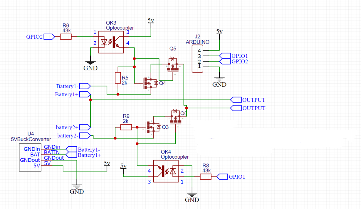
schematic which was used. ignore 5v going into the optocoupler that is now 12v. which is from same buck converter nothing else was added.
I don't know what the problem is. When you measure gate voltage, what it is in reference to? What is the negative meter probe connected to when the positive probe is connected to the gate?
I'm sorry that I don't have an answer for you. The circuit was just my attempt to come up with something that would work, but apparently there's something I don't understand. I suspect the problem may involve the buck converter where you have Battery1- connected to GND. But I just don't see it. Is Output- connected to GND somewhere? Well, perhaps someone else can help.
Thank you for the new schematic. I have not studied every detail but can immediately see problems.
First a minor thing as you did point it out:
Please don't do that, please post a schematic that is, as best as possible, correct, not one with known errors.
Now to the more serious problems that I can see (there might be others). You clearly don't understand that voltage is measured between 2 points, and one of those points is, by convention, 0V or ground unless specified otherwise. Add to that components only see the voltage of the things that they are connected to, they don't know or care about other voltages in other parts of the circuit that they are not connected to. Now to explain how that relates to your circuit.
Both battery +ve are connected together, and you switch battery negative. This is NOT 0V or ground, it is battery negative. To be 0V the battery negatives would have to be connected to 0V permanently, and they are not. Connecting the positives together added to the purpose of the circuit means they are not and cannot be 0V. Q4 and Q5 are supplied with gate voltage from OK3, which is connected to +5V (or +12V), which is referenced to GND (0V). The problem with that is the MOSFET needs a voltage on its gate with respect to its source, so if you are applying +12V to its gate, and the 12V is referenced to 0V, but the MOSFET source is not connected to 0V but to some other voltage then there is not the expected 12V gate - source voltage, but some other voltage that depends on, amongst other things, the state of charge of the battery.
The same problem applies to Q3 and Q6.
You are trying to have the battery circuits separate while at the same time treating them as connected. You can't have it both ways.
So, you are thinking "OK, what do you suggest?". Fair question. At the moment I don't know the answer because I've not done what you are trying to do and not worked through the problem.
To solve this you have to ask yourself where the current is going to flow to get back to where it came from, and pay attention to what voltage is what and what it is measured in respect to.
Edit:
On closer inspection, you say that OK3 and OK4 are fed from 12V not 5V, where does that come from? Is U4 outputting 12V? Aside from that, the problem I describe about applies to battery 2, but not really to battery 1 because battery is connected to 0V via U4. Battery 2 is not and cannot be if the circuit is to do what it is supposed to do.
Edit again:
I don't understand the dual N channel MOSFET thing with the MOSFETs in series like that, connected drain to drain, I can't see what that is means to achieve, or how it can work. It doesn't help that the schematic does not follow the convention of lowest voltage at the bottom, highest at the top, which makes it difficult for me to follow.
Another edit:
Sorry to keep coming back with changes but this is bugging me. The duel N channel MOSFETs in series can't work, unless you (or someone) can point out something I'm missing, either about the circuit or MOSFETs.
Please don't do that, please post a schematic that is, as best as possible, correct, not one with known errors.
Sorry, i have updated the schematic with everything and i promise to not be lazy anymore.

Now to explain how that relates to your circuit.
i had my other probe for my multimeter at GND which should still be fine since OK4 and OK3 are getting their voltage which is referenced back to the ground through U4
On closer inspection, you say that OK3 and OK4 are fed from 12V not 5V, where does that come from? Is U4 outputting 12V?
as in the schematic OK3 and OK4 are given voltage from U4.
It doesn't help that the schematic does not follow the convention of lowest voltage at the bottom, highest at the top
i apologise for this since i don't know how to make proper schematics and these are one of my first ones.
I don't understand the dual N channel MOSFET thing with the MOSFETs in series like that, connected drain to drain, I can't see what that is means to achieve, or how it can work.
As far as I know, @ShermanP put them in series like that because of the body diodes. before the circuit was non-functional if both Q4 & Q3 drains were connected together.
After reading all this and checking my schematic over and over i honestly can't come up with anything else which would fix the problems. what i had thought about is what you explained in your reply that the problem only applies to battery 2 which is not connected to 0V via U4. So here is another schematic in which I have added U6 which is another 12v buck converter and converting voltage from battery 2 so the 12V* is referenced to battery 2- and that will go to pin 3 on OK4 so hopefully it acts the same way as OK3. The GND output of U6 is left floating since Q3 will reference 12V* to battery 2- anyway.

Thanks for the improved schematic. If this is your first attempt then I guess it's pretty good.
I really am not happy with the twin MOSFET thing, but I am going to stop commenting for a little while and see if anyone else has better advice than I have been able to offer.
The dual mosfets were my idea. With only one mosfet on each line, he was getting current flowing somewhere. Then he put diodes in to prevent that, but they got hot. So the dual mosfets have their body diodes in opposite directions, so if the mosfets were off, they were really off, with nothing flowing through the body diodes. (Think of the dual mosfets in the DW01 protection circuit, except the gates are tied together, so both mosfets are on or both are off.)
Well, I guess I should apologize for trying to get this working. In my defense though, my circuit in post #34 had the collectors of the optocouplers connected to battery common +, not to 5V or 12V. But I'm not sure that would make any difference. This just illustrates why people don't like switching the low side of things. Everything is connected to ground at some point, so switching ground is really hard to do correctly. And we haven't even talked about what the load circuit will do, and whether it will be referenced to ground at some point. But in the end, I've concluded that this is above my pay grade. I still think the problem is in the buck converter where one battery negative is connected to ground, but I can't explain what exactly the problem is since it's only one of the batteries. But if I were going to experiment, I would disconnect the buck converter completely, and power the optocoupler inputs from a 9V battery, with resistors, just to see if that made things behave.
Don't be silly, you are making a decent effort to help the OP, nothing to apologise for in my opinion.
Sometimes I have a clear idea in my head of what a circuit should be, but, with apologies to @rasil1127 , in this case I don't. If I come up with something I'll post it.
No need to apologise, ive been more trouble to work with here. there's no rush or anything if you can't come up with anything at the moment that's fine you have already helped me enough already! both you and ShermanP.
1 Like
Hi,
What are the part numbers of all your DC-DC converters?
This is important, because in your world they need to have the outputs COMPLETELY isolated from the 12V input.
Otherwise all the gnds and batt1- and batt2 - will be already connected together.
Also can you make the G, D and S designators on each of the MOSFETS readable, increase font size and make the text BLACK.
I am aware its your first attempts with this CAD and well done, but it needs just some fine tuning.
Thanks.. Tom.. ![]()
![]()
![]()
![]()
Hey tom,
the buck converters are from aliexpress, cheap ones.. they said they where isolated but when i checked they weren't! so i gave up on that.
Also can you make the G, D and S designators on each of the MOSFETS readable, increase font size and make the text BLACK.
Unfortunately, I'm unable to edit that certain parameter since i got the whole mosfet as a "thing"
I'm unable to change it in any way i can only move it around etc..
However, i tried the schematic with 3 buck converters and i think its working. 35.4v and 33v is being switched properly and the mosfets aren't blowing up like before! i need to try and introduce a much larger voltage difference for this to be 100% working.
Hi,
I hope I have interpreted your schematic accurately.
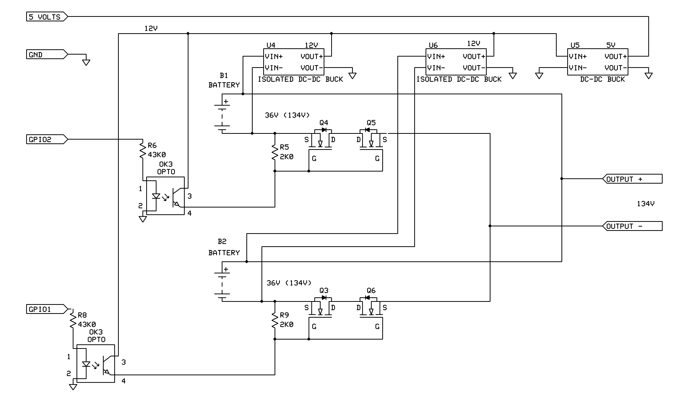
Your problem is you need to switch each gate on with positive gate voltage WITH RESPECT TO EACH MOSFETS SOURCE.
You use a 12V supply that is referenced to a gnd that has no part in either battery circuit, which I would regard as a floating battery circuit because it is not reference to control gnd.
Are you using your DMM to help trouble shoot?
Measure the gate - source voltage on Q4 and Q5 when you select a Battery1, AND then measure the gate- source voltage on Q3 and Q6, which both should be zero volts for your circuit to work.
You basically have your isolated converters in the wrong place, I believe.
Tom.. ![]()
![]()
![]()
![]()
PS. How much current will you be drawing from 134V supply?
PSS. What is the application, what is this part of?
2 Likes
Hey,
Thank you for re-creating my schematic it looks very well done! good job ![]()
I hope I have interpreted your schematic accurately.
i found there's a problem in the circuit which i have circled (Also i have copied your design in my software so i can modify it.)
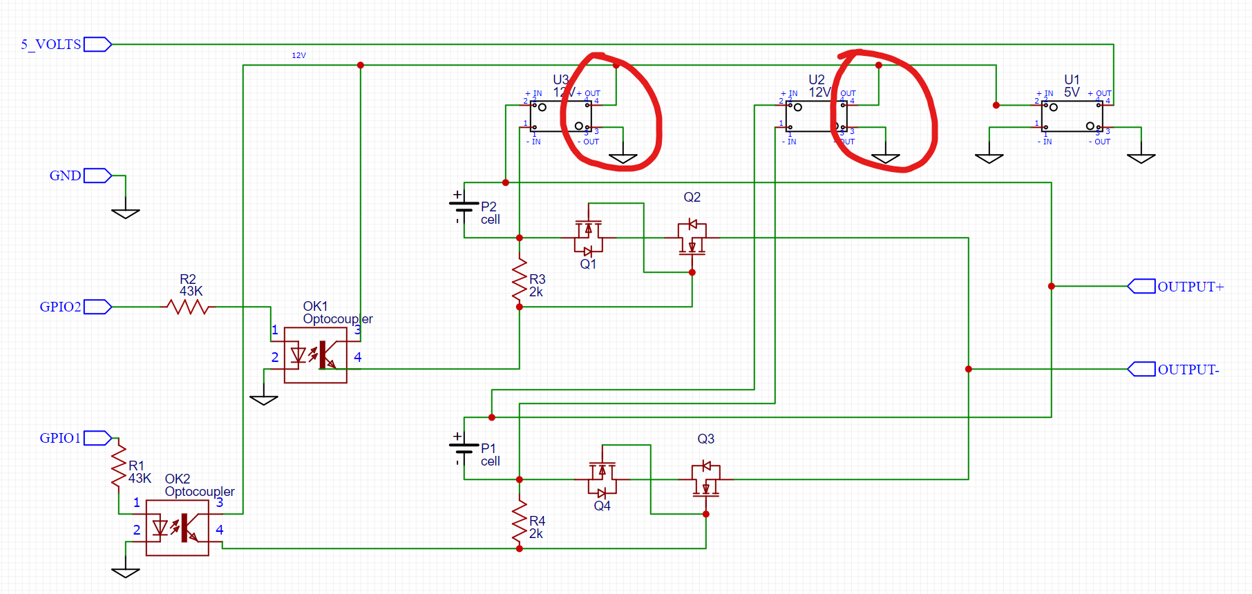
In your schematic, you're using isolated buck converters for converting the battery voltage. however I don't have those, mine say they are isolated but they weren't! they still have a current path. so connecting both grounds to common isn't possible due to different voltage potentials in the circuit introduced by the batteries. I've fixed that to how i have made this circuit in real life here:

Measure the gate - source voltage on Q4 and Q5 when you select a Battery1, AND then measure the gate- source voltage on Q3 and Q6, which both should be zero volts for your circuit to work.
I measured this, and the mosfets which were on had 12v on their gate to source voltage. and the other mosfets didn't have any. and when they were on it was vice versa.
You basically have your isolated converters in the wrong place, I believe.
please have a look at my updated schematic to see if that would be in the correct place.
How much current will you be drawing from 134V supply?
I will be running around close to 20A however, i will add lots of parallel fets in the final design so that it could handle more current since i might want to deploy these on lower voltage circuits too.
What is the application, what is this part of?
this is part of a bike where i could have 2 lithium-ion batteries in parallel while not ever connecting them in parallel. Hotswap capability of batteries. also, the Arduino will tie it into my computer which is located on the bike that manages it.
EDIT: I have created the circuit in real life, and connected batteries which have a voltage difference of 2v and they seem to be switching properly. and nothing is getting hot. However, as soon as i connect batteries which have voltage differences of 16v Q4 and Q3 start to get very hot and soon destroy themselves. I believe this is the 2 batteries trying to equalize and the mosfets blowing up. but why? The gate voltage of OFF mosfets is around 200mv.
(Both of the mosfets are NOT on at any given time they are always switched one after the other.)
(I understand the risks involved in this and all of this is done in a controlled environment.)
Q3 and Q4 are on P1, when does this happen, when which batteries are switched in?
If you switch in the other batteries instead, do the opposite MOSFETs get hot?
What is the gate-source voltage on the hot MOSFETs when they heat up?
Tom... ![]()
![]()
![]()
![]()
Have you tested your irfb4110 mosfets to make sure they don't have reverse current flow at -16V? I know that sounds silly, but just to be sure you don't have some kind of avalanche thing going on.
Edit: I guess that would be 34 + 16 = 50V reverse test.
1 Like