TFT_eSPI: Support added for STM32 processors with SPI DMA

The TFT_eSPI library was originally created to suport ESP8266 and ESP32 processors. It is in the process of being refactored to support other processors, in particular the STM32 series.

The new refactored library here is targeted at any 32 bit processor, but it will now run (slowly) on an UNO if the fonts are limited to GLCD. Performance on 8 bit and 16 bit processors will be poor due to lack of processor specific optimisation and the extensive use of 32 bit variable types.

Summary:

Added support for STM32 boards with SPI or 8 bit parallel displays
Added STM32 targeted optimised drivers
Added DMA for STM32F2xx/4xx/7xx when used with SPI displays
Added three new examples to test SPI DMA on STM32F2xx/4xx/7xx boards

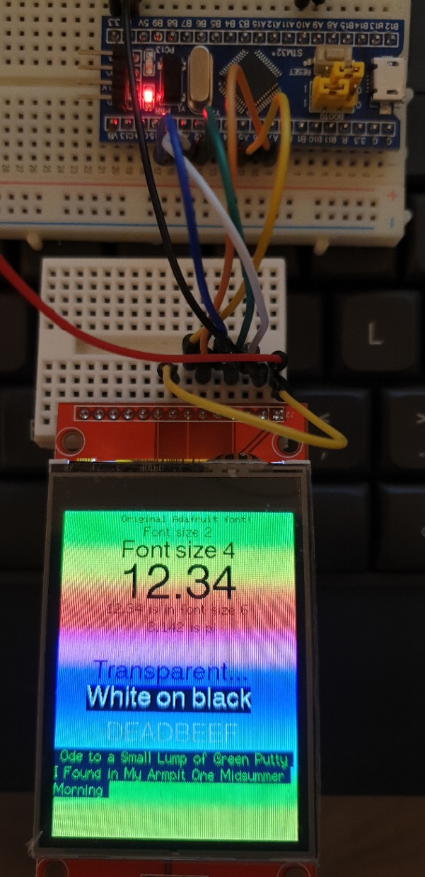
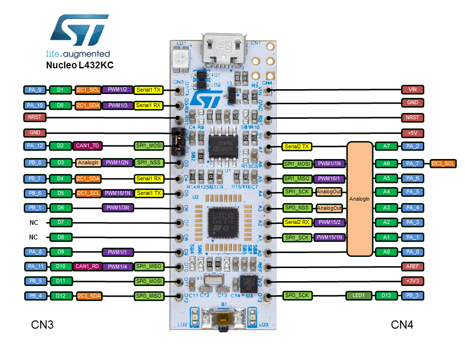
Testing of the updates has been performed with STM32F103 "Blue Pill" plus STM32F401, STM32F446RE and STM32F767ZI Nucleo boards.

Until it is "released" it must be downloaded as a zip file. Smooth fonts are not yet supported for STM32 processors due to the lack of SPIFFS but SD card support will be added.

Please SAVE A COPY of your existing TFT_eSPI library in case you have issues with this new branch.

Performances are quite good:

STM32F767 8 bit parallel ILI9341
Benchmark, Time (microseconds)
Screen fill, 25639
Text, 3968
Lines, 24316
Horiz/Vert Lines, 2258
Rectangles (outline), 1593
Rectangles (filled), 53138
Circles (filled), 16937
Circles (outline), 14347
Triangles (outline), 6273
Triangles (filled), 22635
Rounded rects (outline), 6172
Rounded rects (filled), 60827

Total = 0.2381s

STM32F767 55MHz SPI, STM32 specific driver ILI9341
Benchmark Time (microseconds)
Screen fill 114895
Text 21052
Lines 139092
Horiz/Vert Lines 11158
Rectangles (outline) 7613
Rectangles (filled) 238863
Circles (filled) 80542
Circles (outline) 86984
Triangles (outline) 31905
Triangles (filled) 104423
Rounded rects (outline) 38057
Rounded rects (filled) 276499

Total = 1.1511s

Thanks bodmer, as always giving something else with these ILI9341. We will take a look. Have you considered using the SdFat library as a basis for image management from SD?

Happy Holidays

@TFTLCDCyg

Thanks, I have not looked at SDFat for a while but would be the SD library of choice as it appears the SPI port can be set so the TFT updates can use DMA while SD files are being accessed. This should boost performance for smooth fonts.

I have ordered an STM "blue pill" to test the library with and will be experimenting with SDFat as well.

Feedback on the current version would be appreciated.

My "Blue pill" arrived today so I connected it up to an ILI9341 display and used the STM32 setup edited to use 36MHz SPI clock and the following pin connections:

#define TFT_CS   A1 // Chip select control pin to TFT CS
#define TFT_DC   A0 // Data Command control pin to TFT DC (may be labelled RS = Register Select)
#define TFT_RST  A2 // Reset pin to TFT RST (or RESET)

Also wired power and LED plus:
A5 -> TFT SCK
A7 -> TFT SDI (MOSI)

The simple sketches (e.g. graphicstest) compiled OK and ran fine with good performance.

Some ESP32/ESP8266 sketches are too big for the RAM and/or FLASH size to run on a Blue Pill.

Make sure you have the "official" STM Arduino board support package loaded.

If you are still having problems then post back.

There is pixel aliasing between the camera pixels and TFT in this rather poor picture but it captures the test setup:

Performance is quite good (I tested with latest Adafruit_GFX and that took 35 seconds !!!!):

STM32 Blue Pill 36MHz SPI ILI9341
Benchmark,                Time (microseconds)
Screen fill,              377133
Text,                     70972
Lines,                    426499
Horiz/Vert Lines,         40546
Rectangles (outline),     26729
Rectangles (filled),      785933
Circles (filled),         257208
Circles (outline),        276474
Triangles (outline),      98671
Triangles (filled),       355996
Rounded rects (outline),  120036
Rounded rects (filled),   926630
Total = 3762827us
Total = 3.7628s

I read that the Blue Pill can be over-clocked from 72MHz to 128MHz. Potentially this could lead to unreliable operation and it will affect timings and the USB port will not run. But for some applications this may be acceptable.

EDIT 2: As over-clocking may render the USB port on the board unusable while it is running at 128MHz, it would be unwise to use the USB port to program the Blue Pill as it may then appear "bricked". Only try this if you are using the serial method where programming is done via a serial connection to A9 and A10. YOU HAVE BEEN WARNED!

As they are cheap boards and this is just for testing I though I would give it a try. The code to set to 128MHz is:

void SystemClock_Config(void)
{
  RCC_OscInitTypeDef RCC_OscInitStruct;
  RCC_ClkInitTypeDef RCC_ClkInitStruct;
  RCC_PeriphCLKInitTypeDef PeriphClkInit;

  /* Initializes the CPU, AHB and APB busses clocks */
  RCC_OscInitStruct.OscillatorType = RCC_OSCILLATORTYPE_HSE;
  RCC_OscInitStruct.HSEState = RCC_HSE_ON;
  RCC_OscInitStruct.HSEPredivValue = RCC_HSE_PREDIV_DIV1;
  RCC_OscInitStruct.HSIState = RCC_HSI_ON;
  RCC_OscInitStruct.PLL.PLLState = RCC_PLL_ON;
  RCC_OscInitStruct.PLL.PLLSource = RCC_PLLSOURCE_HSE;
  //RCC_OscInitStruct.PLL.PLLMUL = RCC_PLL_MUL9;           // 72 MHz
  RCC_OscInitStruct.PLL.PLLMUL = RCC_PLL_MUL16;            // 128 MHz
  if (HAL_RCC_OscConfig(&RCC_OscInitStruct) != HAL_OK) {
    while (1);
  }

  /* Initializes the CPU, AHB and APB busses clocks */
  RCC_ClkInitStruct.ClockType = RCC_CLOCKTYPE_HCLK | RCC_CLOCKTYPE_SYSCLK
                                | RCC_CLOCKTYPE_PCLK1 | RCC_CLOCKTYPE_PCLK2;
  RCC_ClkInitStruct.SYSCLKSource = RCC_SYSCLKSOURCE_PLLCLK;
  RCC_ClkInitStruct.AHBCLKDivider = RCC_SYSCLK_DIV1;
  RCC_ClkInitStruct.APB1CLKDivider = RCC_HCLK_DIV2;
  RCC_ClkInitStruct.APB2CLKDivider = RCC_HCLK_DIV1;

  if (HAL_RCC_ClockConfig(&RCC_ClkInitStruct, FLASH_LATENCY_2) != HAL_OK) {
    while (1);
  }

  PeriphClkInit.PeriphClockSelection = RCC_PERIPHCLK_ADC | RCC_PERIPHCLK_USB;
  PeriphClkInit.AdcClockSelection = RCC_ADCPCLK2_DIV6;
  PeriphClkInit.UsbClockSelection = RCC_USBCLKSOURCE_PLL_DIV1_5;
  if (HAL_RCCEx_PeriphCLKConfig(&PeriphClkInit) != HAL_OK) {
    while (1);
  }
}

To invoke the overclock in your sketch, add thet function above to the end of the sketch and then insert the following line at the start of setup():

...
void setup() {
  SystemClock_Config(); // Overclock Blue pill to 128MHz
...

To run with the TFT_eSPI library and an ILI9341 display the SPI clock must be set to 32MHz in the setup file:

#define SPI_FREQUENCY  32000000

Performance comparison to last post:

STM32 Blue Pill 32MHz SPI, ILI9341, CPU overclocked to 128MHz
Benchmark,                Time (microseconds)
Screen fill,              212138
Text,                     39920
Lines,                    239589
Horiz/Vert Lines,         22806
Rectangles (outline),     15032
Rectangles (filled),      441872
Circles (filled),         144490
Circles (outline),        155433
Triangles (outline),      55483
Triangles (filled),       200148
Rounded rects (outline),  67491
Rounded rects (filled),   520425
Total = 2114827us
Total = 2.1148s

The over-clocking also sped up the results with Adafruit_GFX to 19.88 seconds but that is still very slow. Not sure why the Adafruit library is so slow. I used " tft.begin(32000000); // Can set SPI clock rate" so I assume it used hardware SPI rather than bit bashing.

EDIT 1: In practice just including the SystemClock_Config() function code in your sketch will cause it to run. You do not need to call it up in setup(). The reason it runs is that it is a copy of a function in the board package for the Blue Pill and the function in the package is marked "WEAK", this means that the copy in the sketch is run in preference. To resume to 72MHz you must rename or delete the overclock function in the sketch.

I'm curious about the results of your library in STM32; over there are an F767 core and since a few days a blue pill, but I must confess, I still don't have an ILI9341 to connect, possibly it comes in a rowing boat from the east lol...

The blue pill just arrived but I did not resist and I installed the FT813 of 3.5" screen before the ILI9341 XD. As soon as I have a piece of 9341 in my hands, I will take a look at the library you have shared with us.

I have updated the TFT_eSPI library STM32 branch. DMA capability has been added for the STM32F103 "Blue Pill" boards, this can boost performance in applications where the processor can do useful work in parallel with display updates.

For example, the Blue Pill test results for the frames per second (fps) in the "Boing" demo are:

Blue Pill - 36MHz SPI *no* DMA 36 fps
Blue Pill - 36MHz SPI with DMA 67 fps
Blue Pill overclocked to 128MHz *no* DMA - 32MHz SPI  64 fps
Blue Pill overclocked to 128MHz with DMA - 32MHz SPI 116 fps

So the low cost STM32 board can match the performance of this demo.

STM32 and generic processor support has now been added to the TFT_eSPI library Master.

Support for ST7796 displays has also been added.

The TFT_eSPI library has been raised to 2.0.0.

It has been updated to include 4bits per pixel Sprites with a palette table. This allows any 16 colours to be used and changed later to be any set of 16 bit colours. Three new examples have been added for the 4 bit Sprites. A default palette is included, see new "Transparent_Sprite_Demo_4bit" example.

The testing of the library with Nucleo and STM32 boards has not shown up any bugs so far so I think it is now a stable version.

The new MHS displays have proved to be very reliable at high SPI clock rate (80MHz with ESP32) and they appear to be available in other screen sizes with other drivers. The support for RPi displays in the library has therefore been expanded to support other TFT driver chips.

A new option has been added for STM32 processors to optimise performance where Port A (or B) pins 0-7 are used for the 8 bit parallel interface data pins 0-7 to the TFT. This gives a dramatic 8 times better rendering performance for the lower clock rate STM32 processors such as the STM32F103 "Blue Pill" or STM411 "Black Pill" since no time consuming data bit manipulation is required. See setup file "User_Setups/Setup35_ILI9341_STM32_Port_Bus.h".

Example "graphicstest" performance for "Black Pill" (STM32F411CE) based board with 320x480 ST7796 display:

Benchmark,                Time (microseconds)
Screen fill (5 times),    68634
Text,                     7472
Lines,                    85252
Horiz/Vert Lines,         5935
Rectangles (outline),     3749
Rectangles (filled),      167278
Circles (filled),         54451
Circles (outline),        48373
Triangles (outline),      19292
Triangles (filled),       71536
Rounded rects (outline),  18392
Rounded rects (filled),   190152
Total = 740516us
Total = 0.7405s

I have repeated the above test for the 240x320 ILI9241, the "graphicstest" performance for "Black Pill" (STM32F411CE) based board using Port A pins is:

Port A bus ST32F411CE Black Pill ILI9341
Benchmark,                Time (microseconds)
Screen fill (5 times),    34364
Text,                     7471
Lines,                    43092
Horiz/Vert Lines,         3077
Rectangles (outline),     2272
Rectangles (filled),      71284
Circles (filled),         27104
Circles (outline),        24564
Triangles (outline),      10838
Triangles (filled),       33425
Rounded rects (outline),  10169
Rounded rects (filled),   82894
Total = 350554us
Total = 0.3506s

Hi Bodner, how are you? I have difficulties configuring the library for the STM32F103CBT6 Cortex-M3 board (maple mini) will you be able to help me? I would be very grateful.

The pin labels on the PCB do not correspond to the standard port names so you will need to use the port and pin as a reference. Use the setup file "Setup32_ILI9341_STM32F103.h" exactly as it is except comment out the TOUCH_CS line, and then wire pins as follows:

TFT SCK pin to Maple pin 6 (this is port pin PA_5)
TFT MISO pin to Maple pin 5 (this is PA_6)
TFT MOSI pin to Maple pin 4 (this is PA_7)

TFT CS pin to Maple pin 11
TFT DC/RS pin to Maple pin 10
TFT RST pin to Maple pin 9

Also wire up the power lines VCC and GND.

Get the display working first before progressing to try to adding or wiring up a touch controller.

Hi Bodner, Thanks for the useful post.

I have tried the library on ESP32 and i works great. I wanted to now try in on STM32 and purchased the 2 boards:

  1. NUCLEO-L432KC
  2. NUCLEO-F446RE

I have created the board file (setup_L432KC) as you mentioned in the above post:

#define STM32
#define ST7789_DRIVER
#define TFT_CS A0
#define TFT_DC A2
#define TFT_RST A7
#define TFT_MISO A5
#define TFT_MOSI A6
#define TFT_SCLK A4
#define SMOOTH_FONT

#define SPI_FREQUENCY 36000000 // 36MHz SPI clock
#define SPI_READ_FREQUENCY 12000000 // Reads need a slower SPI clock
#define SPI_TOUCH_FREQUENCY 2500000 // Must be very slow

But the display is not showing anything. Please suggest if i have used the wrong pins.

Also please see the setup (Attached code Read_User_Setup_STM32L432KC.ino):

User setup output (it shows wrong pins):

TFT_eSPI ver = 2.2.0
Processor = ESP815
Transactions = Yes
Interface = SPI
Display driver = 7789
Display width = 240
Display height = 320

MOSI = D23 (GPIO 23)
MISO = D19 (GPIO 19)
SCK = D18 (GPIO 18)
TFT_CS = D15 (GPIO 15)
TFT_DC = D2 (GPIO 2)
TFT_RST = D4 (GPIO 4)

Font GLCD loaded
Font 2 loaded
Font 4 loaded
Font 6 loaded
Font 7 loaded
Font 8 loaded
Smooth font enabled

Many Thanks

Read_User_Setup_STM32L432KC.ino (7.12 KB)

The pins look OK for the L432

Check the User_Setup_Select.h file is pointing to only one configuration and it is the one you want to use.

At the moment it is picking up the wrong setup.

The Read_User_Setup has been updated in the latest Github version.

Thanks Bodmer.

I have updated the User_Setup_Select.h file and added include as:

#include <User_Setups/Setup32_ST7789_STM32L432KC.h>

After using the Read_User_Setup you have mentioned i am getting better output :

TFT_eSPI ver = 2.2.0
Processor    = [b]STM32[/b]
Transactions = Yes
Interface    = SPI
Display driver = 7789
Display width  = 240
Display height = 320
MOSI    = GPIO 77
MISO    = GPIO 66
SCK     = GPIO 55

>>>>> Note: STM32 pin references above D15 may not reflect board markings <<<<<
TFT_CS   = D5
TFT_DC   = D6
TFT_RST  = D9
Font GLCD   loaded
Font 2      loaded
Font 4      loaded
Font 6      loaded
Font 7      loaded
Font 8      loaded
Smooth font enabled

Display SPI frequency = 36.00

I updated pins as shown below as i was getting error for A7 pin. So used D pins now for CS DC and RST.

My Setup32_ST7789_STM32L432KC:
#define STM32
#define ST7789_DRIVER
#define TFT_CS D5
#define TFT_DC D6
#define TFT_RST D9
#define TFT_MISO PA_6 // A5
#define TFT_MOSI PA_7 // A6
#define TFT_SCLK PA_5 // A4

Screen still does not show anything. I used the Colour_Test to debug, and serial print stops after:

tft.fillScreen(TFT_BLACK);

So it seems some where there is an issue with my setup. Hope you can provide some direction.

Colour_Test_STM32L432KC.h.ino (3.79 KB)

Hi Bodner,

How are you?

I have difficulties configuring the library for the NUCLEO-F446RE will you be able to help me? I would be very grateful.

I am using these pins, but not able to get the display working.

CS PB_5(D4)
DC PA_8(D7)
RST PA_10(D2)
MISO PA_6(D12)
MOSI PA_7(D11)
SCLK PA_5(D13)

I suggest you adapt Setup29_ILI9341_STM32.h and include it in the User_Setup_Select.h file (// Only ONE include line should be uncommented.)

Hi Bodmer
I am trying to test an ILI9341 display with your library in an STM32F411 blackpill.
I am trying the graphictest example.
I have tried many setups but the screen does not show anything.
Can you please give me the pin connection and the right setup file?
Thank you.

First off. It is wise to post a link to the actual board that you have bought. e.g. this board

I presume that you have tried many SPI applications on your board.

From C:\Users\David Prentice\AppData\Local\Arduino15\packages\STM32\hardware\stm32\1.9.0\variants\Generic_F411Cx\variant.h

// SPI definitions
#define PIN_SPI_SS              PA4
#define PIN_SPI_SS1             PA4
#define PIN_SPI_SS2             PB12
#define PIN_SPI_SS3             PA15
#define PIN_SPI_SS5             PB1
#define PIN_SPI_MOSI            PA7
#define PIN_SPI_MISO            PA6
#define PIN_SPI_SCK             PA5

So the default SPI would be on PA4-PA7
And you could use any GPIO for TFT_DC and TFT_RST

Adafruit_ILI9341 should work too. And you can use the bit-bang Adafruit_ILI9341 constructor with random GPIO pins.

I would start with the Adafruit_ILI9341 bit-bang constructor to verify your wiring.
Then verify with bit-bang SPI1 wiring
Finally verify the SPI1 wiring with the HW SPI constructor.

Once verified, setup the pins in your User_Setup and run Bodmer's examples.

The Official STM32 core has many options to choose in the IDE. Please quote what you are actually using.

David.