As a beginner i'd appreciate a second opinion but i think i know the answer, i think i fried it! I built up a project, it was fine on the bench, installed it but it won't communicate. Project is a Mega with ethernet shield that reads binary I/O from an alarm via a bank of optocouplers. As i say great on the bench but nothing once it was in. Nothing on ethernet (no ip in my router) and nothing when i have stripped it all out again and connected the board up on USB. Green LED on and Pin 13 led is static, and the voltage at 3 and 5v pins is present, correct and stable.
I tried the loopback test below but still nothing. I'm guessing i have made a mess of something. Suspect maybe i have failed to keep the two 'sides' of the optocoupler away from each other in the wiring.
Post a schematic, not a frizzy picture showing all of your connections including power and ground. Also post links to the technical information on the hardware items not sales info.
Ok, with advance apologies for my schematic.. and I missed of my photocell feed which goes to pin A1, taken before the resistor.
As a beginner the bits I thought are suspect are the earth of the photocell at the optpcoupler, and the earth of the optocoupler at the barrel jack, hence the two sides are not separate.
The only difference from the bench is that the power (12v) is from the alarm panel rather than a bench supply, and when I powered up all the alarm outputs were ‘on’, where I had only tested one at a time.
The cost of a new board is no disaster, but the learning is important so many thanks for the help.
Quick edit to my post there to sort the last photo.
I have stripped it off the wall now so it’s half built/stripped on my desk. I didn’t check the barrel, but the output on the alarm panel where I took the power from is marked as 12v. I will have to check my sketch on the pullup resistor but I think so. Worked ok on the bench.
Data is read in to the mega. It is watching the optocoupler for a signal, which then turns on the mega’s pin.
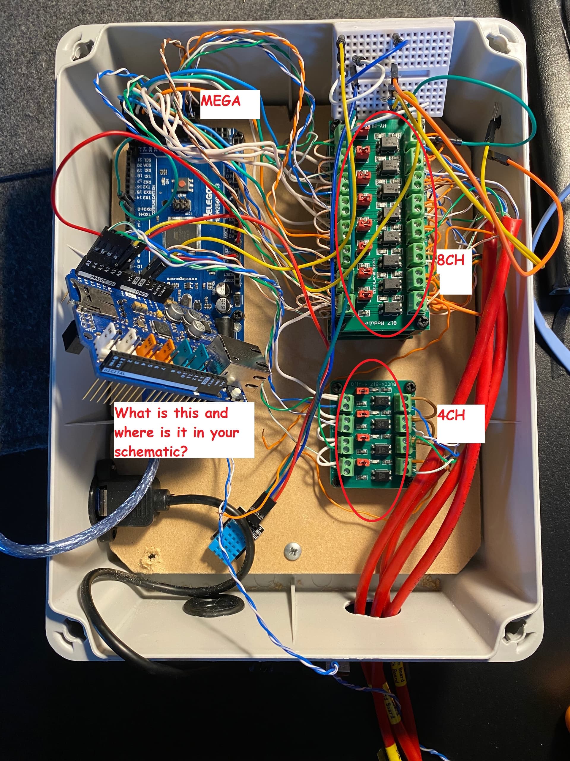
I will post a pic of the box as it stands (it’s a mess, I know!) and look up the optocoupler details.
Ok so a mess as I say! Few things:
The green wire from the breadboard to the optocoupler at top right is the photocell earth. The two orange wires with bare ends bottom centre are the optocoupler earths which were connected to the barrel jack.
A schematic of the 4 channel optocoupler can be found here. I have 3 x 8 channel boards and 1x4. They are all wired into the mega and working on the bench, but only 2 of the 8’s were connected up at ‘time of death’.
That’s the Ethernet shield - it’s just hanging around because I stripped everything down to test the bare mega. Still no comms from the mega when connected on the bench via usb or the barrel so I don’t think the power supply from the alarm panel is the issue.
Ethernet off the shield (before I took it off). Not sure on the ide version but it’s the one it was ok on 7 days ago, windows 10. Also tried the online ide and a version I have on a Mac. Nothing on any of them.