@rogerlette
Please post a pdf of the schematic.
A link to a kicad pcb file is useless to those who don't have that version of kicad.
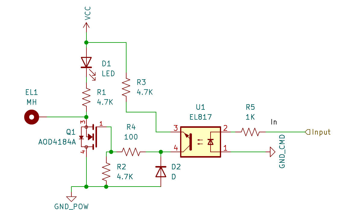
There is no Zener diode in the circuit, do you mean the schottky diode?
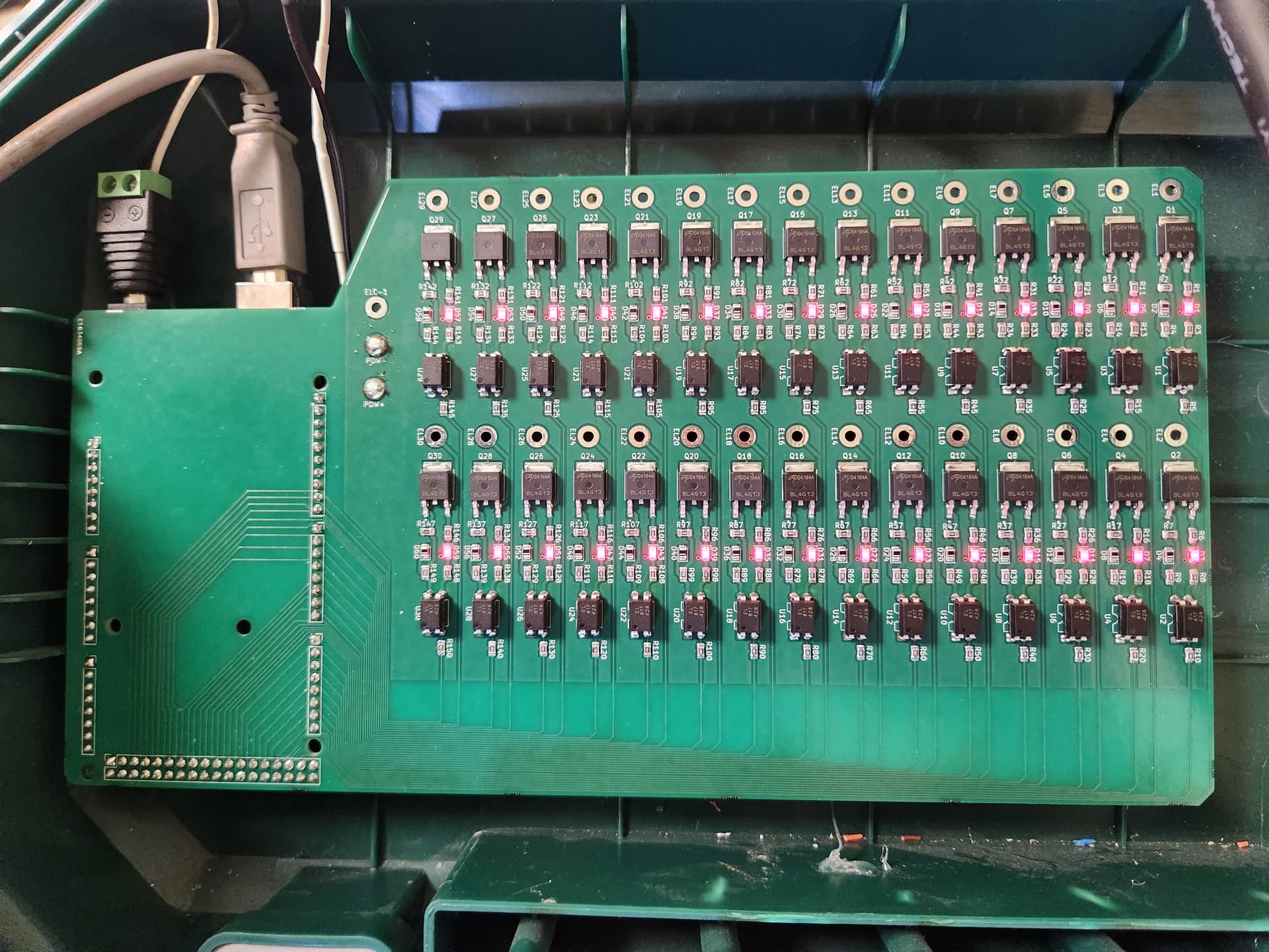
Looking at the photograph of the PCB, it looks to me as though you have at least two mistakes (x30) :
The pins of the opto isolators are transposed.
The source and drains of the MOSFETs are transposed.
On the schematic that you are copying, the Arduino output connects to pin 1 of the opto-isolator (via a resistor). You have it going to pin 2. - This means that the LEDs in the opto-isolator are connected the wrong way round.
Similarly pins 3 and 4 are swapped about.
The tab of the MOSFET is the drain, you have it connected to GND, where the source should be. The LEDs (and output pins) are connected to the source, not the drain of the MOSFETs.
The MOSFETS have an internal diode between drain and source, it is normally reverse biased, but by having drain and source transposed they become forward biased, hence putting the LEDs on.
I did test with a simple blink program, and I even check the input of the optocoupler with a multimeter, and it correctly display 5V when the output are set to HIGH, and 0V when set to LOW.
I assume I need a zener diode according to this topic : arduino forum
John, thank you very much, I indeed swap the components.. So stupid..
Since I'll have to re-print the board, can you tell me if I need a zener diode or not ?
Does the other components seems ok to you ?
I think that the zener was put into the original design to give it the wide operating voltage of 6V - 36V.
As you are using the circuit at 24V it is probably not necessary, though having it fitted won't do any harm.
If the only error had been the opto-isolator, you could have got round the problem by mounting the component on the other side of the PCB.
Did you not check the schematic against the one you were copying from before doing the layout?
A 12V zener diode would protect the MOSFET gate from any transients, so a good idea but more importand is the flyback diode which you do not have on your board.
Post your new schematic before you make the next board.
I have to say that it was my first time with Kicad, my first time selecting components, I struggle with many details, I had to do and re-do several time the schematic, and I finally did stupid mistakes..
Anyway, Jim I will follow your advice for sure and I will post my schematic before printing the next board !!
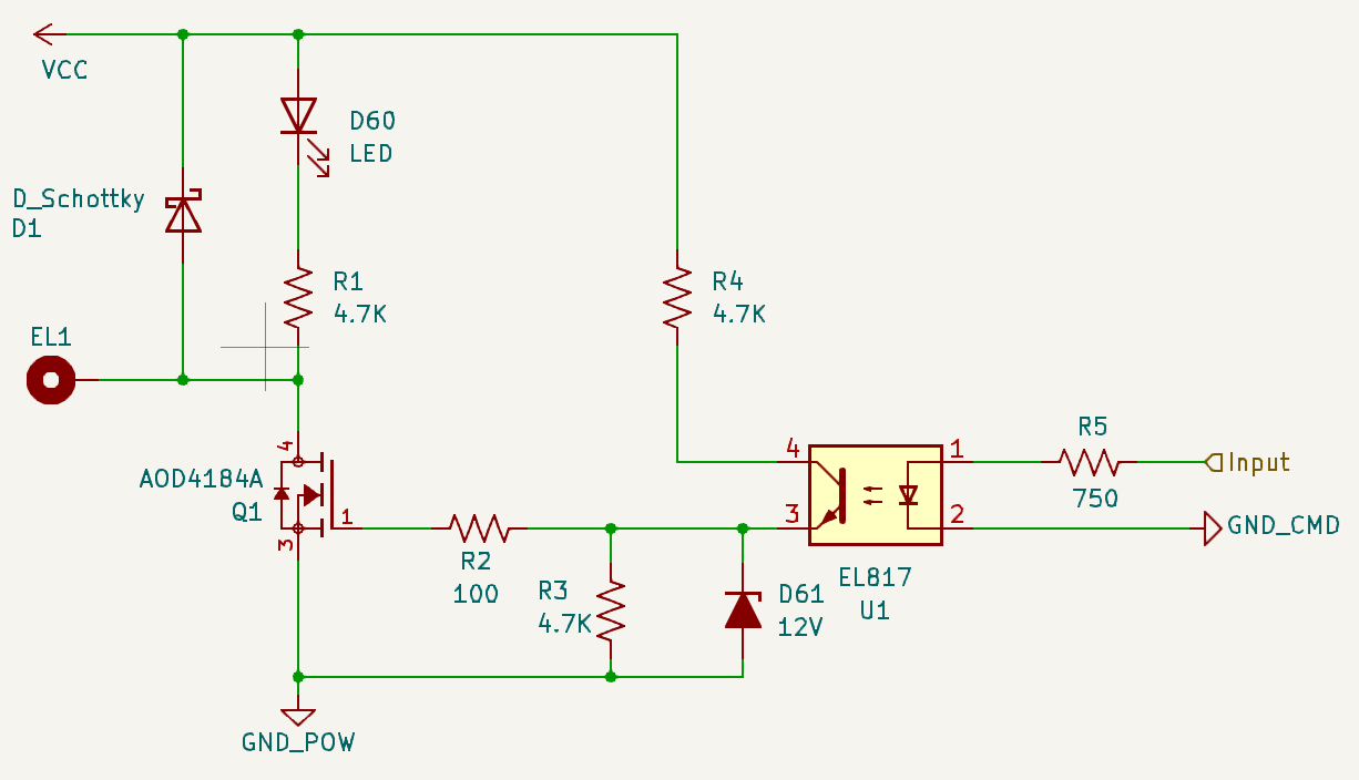
This is a more conventional way to draw a schematic
Notice that it is almost identical to the protosupply schematic.
I changed the 1K resistor to 750 to ensure thet the 817 get 5mA
I think the 4.7k resistor feeding the optocoupler (and eventually the MOSFET gate) is too high a value. With the other 4.7k resistor going to ground, you have a voltage divider that will only put HALF of VCC on the gate. That could be enough, or maybe not.
I don't think you need that resistor at all, actually (not the Zener or any diode in that position, either.) But something around 470 ohms would be OK.
(Another alternative would be for the 4.7k resistor going to ground to be a much higher value, like 47k.)
Zener diode:
Use this zener. Here is why, it is 14V 5% so the actual voltage will be somewhere between 13.3 and 14.7. Since the MOSFET gate is +/-20V it is low enough to protect the MOSFET but higher enough to make sure the gate voltage is 12V.
Schottky diode:
Schottkys are faster than silicon and are no more expensive.
Here is the updated schematic, it should be exactly the same as yours.
Thanks for you help choosing the components, it's really not easy to be sure of what I'm doing...