There is a recurring theme of people new to Arduino and/or microcontrollers not grasping the concept of putting what I call ‘building blocks’ of code together to achieve some goal. These short sketches are an attempt to offer some examples showing how small pieces can be used in concert to build up larger, more complex sketches.
Thanks to @PerryBebbington and @ballscrewbob for support and input. You made it better.
The examples will illustrate:
• Doing ‘several things at once’
• pitfalls of blocking code using delay() and while()
• Operating millis()† timers
• Enabling and disabling sections of code
• Using ‘state change detection’ < IDE -> file/examples/digital/statechangedetection to…
• increment a counter which…
• toggles a boolean which enables/disables…
• a time-driven Finite State Machine (FSM) to blink an LED
Also touched on: local scope variables, calling functions with and without arguments, using analog pins for digital input and output1, enums, static.
Gound Rules:
These sketches were developed with the Arduino IDE version 1.8.13.
† (dagger) denotes a footnoted link to the Arduino Reference Page where an item is explained and often an example is shown.
The main text will cover ‘just the facts’. Supercripted numerals 1, 2, 3... denote footnotes to a more detailed explanation of something in the main text.
Variables2 used in the sketch(es) are colored blue.
Although it’s not strictly correct, for our purposes here the terms true, HIGH, and 1 (or, one) are synonymous. Likewise for false, LOW, and 0 (or, zero).
An editing tip: Some of the sketches will need minor changes and certain code disabled by commenting out. On a PC you can comment out a line by placing the editing cursor anywhere on the line and using the sequence <ctrl> forward slash ( / ). If several lines need commented highlight as if to copy/cut and then forward slash. Don’t forget to upload the changes.
We’ll start with a basic pushbutton-operated timer and add on to it. If you don’t have a pushbutton handy a simple breadboard jumper, or failing that, a piece of solid 22 ga. hookup wire, will suffice. Push one end of the wire into the Arduino GND socket and touch the other end to the input pin, that’s all the switch is doing anyway. The switch is connected as S3 is to D3 A31 and the LED is connected as D2 is connected to D7 A0 are in the drawing. If all you’ve got is the Arduino and no breadboard the external LED can be omitted, it just makes seeing the variable status easier.

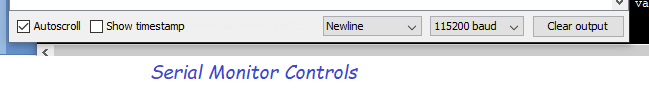
To begin, select, copy, and paste the code below into a new IDE sketch and upload it to the processor. Start the serial monitor by clicking on the magnifying glass icon in the IDE upper right corner. Insure the baud rates in the sketch Serial.begin(115200)† and the serial monitor match.
// Runs on an UNO

// A basic timer that runs when enable is true, else is reset.

// Demonstrates:
// millis() timer operation
// sensing/indicating timer completion
// doing more than one thing at a time

// THIS Version puts the starting display in loop() for variable passing example


uint32_t timer1AccValue;
uint32_t const timer1Preset = 1500; // 1.5 seconds
uint32_t timer1PreviousMillis;
uint32_t timer1CurrentMillis;
bool isTimer1TimedOut;
bool isFirstPass;

const byte enablePin = A3; // A0-A5 can be used as digital inputs
const byte externalLED = A0;
//
//-----------------------------
//
void setup() {
  Serial.begin(115200);
  pinMode(enablePin, INPUT_PULLUP); // INPUT_PULLUP avoids the need for a discrete resistor.
  pinMode(LED_BUILTIN, OUTPUT);
  pinMode(externalLED, OUTPUT);
  isFirstPass = true;
while(digitalRead(enablePin));
}

void loop() {
  while (isFirstPass) {
    Serial.print("\n\nTimer  Timer\n");
    Serial.println("Value  Done");
    displayFunction(timer1CurrentMillis - timer1PreviousMillis, isTimer1TimedOut);
    delay(6000); // Pause for user to see column headings
    isFirstPass = false;
  }
  bool isButtonPressed = (bool) !digitalRead(enablePin); // check button state before proceeding
//  digitalWrite(LED_BUILTIN, isButtonPressed);
//  digitalWrite(externalLED, isButtonPressed);

  timer1CurrentMillis = millis(); // Take a snapshot of millis() to use for processing.

  if (isButtonPressed) { // If input is grounded, enable timer to run.
    // Set the timer's completion status
    if (timer1CurrentMillis - timer1PreviousMillis >= timer1Preset) { // If time elapsed set isTimer1TimedOut
      isTimer1TimedOut = true;
    }
  }
  else {  // If timer not enabled it is reset
    timer1PreviousMillis = timer1CurrentMillis; // Reset the timer.
    isTimer1TimedOut = false;
  }
  //
  // End of timer1 update activities
  //
  digitalWrite(LED_BUILTIN, isTimer1TimedOut);  // Send timer1's completion status to the onboard LED
  digitalWrite(externalLED, isTimer1TimedOut);

  displayFunction(timer1CurrentMillis - timer1PreviousMillis, isTimer1TimedOut);
} // end of loop

//--------------------------------------------

void displayFunction(uint32_t timer1, bool timedOut) {

  // Display runtime values passed from caller
  Serial.print(timer1);
  Serial.print("\t");
  Serial.print(timedOut);
  Serial.println();
}
1 The keywords and functions for the digital I/O pins apply also to the analog pins. This makes it perfectly legal and harmless to connect our button to an analog input defined by enablePin and configure it in setup()† via pinMode† and control or access it with digitalRead/Write†. Just substitute A0-A5 in place of the usual pin number.
2 A piece of advice: Variables, constants, functions, etc. should be given descriptive, meaningful names so others, including your six-months-from-now self, can more easily determine what’s going on with the code. Cryptic, one- or two-letter names are a false economy and the compiler doesn’t care about name length. Don’t imagine you’ll remember a few weeks from now what px = py + ( ry * 673) means without scuffling through the code trying to find a declaration. Besides, the names have no existence when the code does go down to the chip anyway. Giving things names also avoids magic numbers and reduces the need to comment the code.