I have a 'go to' opto isolated DMX PCB I use for my various projects. Just needs a serial connection and a HIGH/LOW signal for direction.
Works a treat on any Arduino processor and also on my own designed dedicated DMX driver board that includes a 328p processor.
I can also use it fine with a Teensy 4.1
But... absolutely no go with an ESP32. I have tried all the libraries and burnt MANY hours trying to get it to work. Nothing.
None of the examples in any of the libraries work... whether dedicated ESP32 DMX libraries (of which there are not many), or Arduino libraries that I have tried to alter.
It seems to be a timing thing. Sometimes, the attached DMX light will flicker.... but it's never worked correctly.
Anyone one have a lead to a decent ESP32 DMX library? I have struggled to find a decent one.
Any idea what timing issue (if that is what the problem is) might be?
I can't post code... as I basically don't have any. I just try the library demos.
I have noticed you must declare the serial port pins (not just serial.begin).
The Adafruit DMX library was the closest to working.... but not quite.
(My DMX board is very similar to this)
Also tried this.... nope.
As soon as I connect the DMX board serial back to an Arduino or Teensy... works immediately
Annoying, as I have a nice touchscreen PCB I use and I would like to add DMX
I am using that one successfully, though admittedly not fully to my liking.
It is stable though and the provided examples work. Biggest issue i have is that during transmission some tasks can not be executed due to the nature of the use of FreeRTOS and the memory caching (i think)
Still you should be able to get it to work properly. How about posting the sketch that you are using and let me have a look.
The problem with the ESP32 is the rather complicated UART and FIFO that comes with it, which mainly confuses reception / break detection. I have recently been trying to add DMX out to the I2S mode of Neopixelbus but although the results are very promising, so far it is not glitch free and the author lacks time to review and sort out the last bit to solve that. (There is a fully working DMX out for the ESP8266 using I2S though)
That was also a bit my problem.
I haven't actually tried that one, will do when i find some excess developing time.
Looks like it is using DMXsimple.h which is a bit-banged method, which may work, but will have to disable interruots for reliability and as such will interfere with WiFi in the long run. Chances are it will work properly when you disable interrupts for the transmission stage, still i don't think a UART method is the way to go.
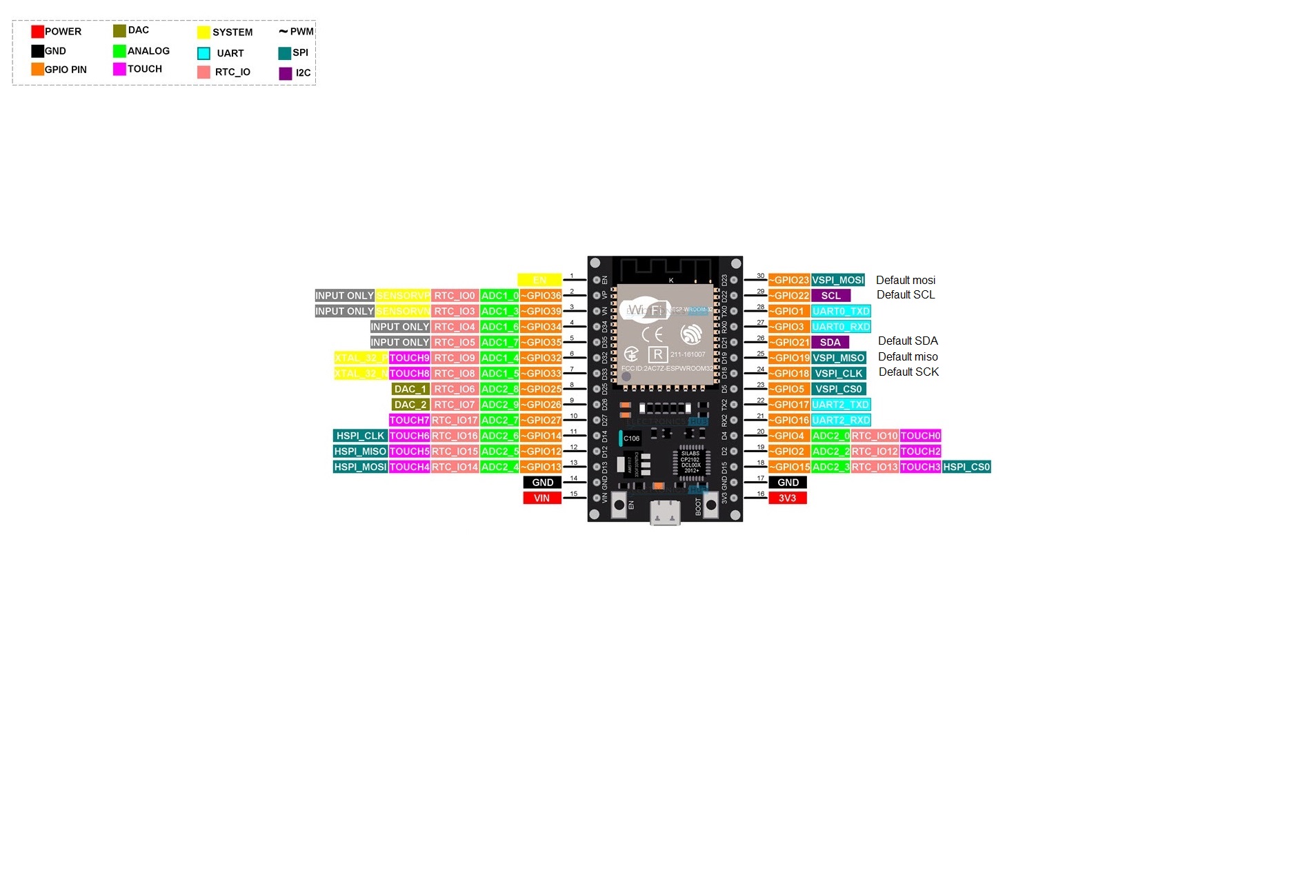
The UART pins on an ESP32 are freely assignable, but not all pins may work for you. The default pins for UART0 (GPIO 1 & 3) are connected to the USB to TTL converter which disturbs reception, the default pins for UART1 are connected to FLASH and aren't useable at all. For esp-dms the direction pins must be a valid output pin.
Anyway post the exact sketch(es) you have tried and i will try to get them working for you. esp-dmx is your best bet for now.
Thanks for the reply.
I will delete all my DMX libraries and re-install, as it's entirely possible that me messing about with them has changed something (or I have not put something back).
I have to say, I don't really like the ESP32. Too many things seem to trip it up. Wifi disables this, Bluetooth stops that, this pin is useless at boot etc
I'll have another go this weekend with the ESP_DMX.
Thank you for the advice and I will report back...
It's a tricky but powerful processor. It does have quite a lot of options. 3 hw UARTs a whole bunch of pins 2 user available SPI busses, 2 DACs , 2 Cores. WiFi BLE etc. but yes to get it to work properly in some cases can be tricky.
DMX turned out to be a bit hard for me. Usually if i read through a library SRC i find most makes sense, but with the ESP32 the UART FIFO was completely beyond me, both for transmission and reception, i can not quite figure out how it works and how i can control it, but this somewiseguy does. Unfortunately he is using the 2nd core for some of the tasks and that means that the 'cached memory' can be affected when there is other routines running that do something similar (I think) . The basic system works flawlessly though.
I am using ESP32 to create an Art-Net node driving WS2812b's and wanted to add a DMX out and also still have a DMX in. (as a sub mode) For this the ESP32 is great, but the DMX part was more tricky than it is on most. Mind you it was pretty tricky on an ESP8266 as well, which eventually caused me to donate to Makuna Neopixelbus to motivate the author to write a DMX out encoding for use with the I2S DMA, which is a method that runs fully in the background once the encoding is complete (Direct Memory Access) There is also DMX ledstrip (WS2821) or that is there used to be, they hardly exist for sale these days, but some people still have them. This DMX out on the ESP8266 is perfect !
During the last couple of months there was an update of Neopixelbus for the ESP32 which opened the door to add DMX out encoding to it, and although also this library's SRC is rather complex and some parts are beyond me, i figured out how to add the encoding and it works, but there is a small glitch which i can not explain and probably doesn't have anything to do with the encoding, but the author of the library has had some setbacks in his private life (something with a tree on his house) so he is a little caught up with that, but will look into it all once he has time and motivation for it.
Again this is a preferred method as an output, since it works fully in the background, and the ESP32 has 2 I2S busses (one for each core) and Neopixelbus even has a parallel mode which allows you to transmit 8 (or even 16) channels simultaneously. So anyway i decided to be patient and wait until the details are sorted.
DMX IN is a different matter. DMX sends 513 channels (or less) and then has a minimum of 88us break, which resets the channel counter. To do this break detection is always the issue with any device used for reception.
With an AVR you can simply monitor the pinState of the RX pin and if it's LOW for that time you can decide on the break found and start receiving on the UART. With an ESP8266 things are a little more tricky already since the GPIO is either connected to the UART or used as a GPIO, but not both at the same time. And as i said before, the ESP32 has a UART rx (and tx) FIFO which is huge (over 100 bytes) and has all sorts of control interrupts and settings. Reading up on it i even found that there are people who have resorted to adding an SPI UART that can be programmed separately, and i can understand this is not a bad idea. I am still considering this for DMX reception. It could be as simple as an Atmega 328p, a minimum of 1KB RAM and a hwUART i think is needed (could be that less RAM would also suffice) But again the complications ... Anyway i am in no rush for DMX OUT
My ESP32 does more or less what i want it to do, and i think the esp-dmx will work for you without to much issue.
I just dug out a new ESP32 C6 Zero. Nice little bit of kit but just doesn't program from any version of the Arduino IDE.
It programmed once and now constantly throws up unrecognised device (which apparently is a thing).
Yea... ESP32's
So... latest IDE. You press the ESP32 C6 Zero 'boot' button and then plug in the USB lead.
It shows up in the IDE and you can program it once.
It finishes, but doesn't run. Pressing 'reset' again then runs the code you uploaded, but also kills the USB link to the PC, so you can never use the serial monitor.
You have to repeat the above process to load any further code.
So I installed the esp_dmx library and it doesn't even compile. Why the heck don't they check these libraries to make sure they actually work.
/*

  DMX Write

  This sketch allows you to write DMX data to a DMX listener using a standard
  DMX shield, such SparkFun ESP32 Thing Plus DMX to LED Shield. This sketch was
  made for the Arduino framework!

  Created 10 September 2021
  By Mitch Weisbrod

  https://github.com/someweisguy/esp_dmx

*/
#include <Arduino.h>
#include <esp_dmx.h>

/* First, lets define the hardware pins that we are using with our ESP32. We
  need to define which pin is transmitting data and which pin is receiving data.
  DMX circuits also often need to be told when we are transmitting and when we
  are receiving data. We can do this by defining an enable pin. */
int transmitPin = 17;
int receivePin = 16;
int enablePin = 21;
/* Make sure to double-check that these pins are compatible with your ESP32!
  Some ESP32s, such as the ESP32-WROVER series, do not allow you to read or
  write data on pins 16 or 17, so it's always good to read the manuals. */

/* Next, lets decide which DMX port to use. The ESP32 has either 2 or 3 ports.
  Port 0 is typically used to transmit serial data back to your Serial Monitor,
  so we shouldn't use that port. Lets use port 1! */
dmx_port_t dmxPort = 1;

/* Now we want somewhere to store our DMX data. Since a single packet of DMX
  data can be up to 513 bytes long, we want our array to be at least that long.
  This library knows that the max DMX packet size is 513, so we can fill in the
  array size with `DMX_PACKET_SIZE`. */
byte data[DMX_PACKET_SIZE];

/* This variable will allow us to update our packet and print to the Serial
  Monitor at a regular interval. */
unsigned long lastUpdate = millis();

void setup() {
  /* Start the serial connection back to the computer so that we can log
    messages to the Serial Monitor. Lets set the baud rate to 115200. */
  Serial.begin(115200);

  /* Now we will install the DMX driver! We'll tell it which DMX port to use,
    what device configuration to use, and what DMX personalities it should have.
    If you aren't sure which configuration to use, you can use the macros
    `DMX_CONFIG_DEFAULT` to set the configuration to its default settings.
    Because the device is being setup as a DMX controller, this device won't use
    any DMX personalities. */
  dmx_config_t config = DMX_CONFIG_DEFAULT;
  dmx_personality_t personalities[] = {};
  int personality_count = 0;
  dmx_driver_install(dmxPort, &config, personalities, personality_count);

  /* Now set the DMX hardware pins to the pins that we want to use and setup
    will be complete! */
  dmx_set_pin(dmxPort, transmitPin, receivePin, enablePin);
}

void loop() {
  /* Get the current time since boot in milliseconds so that we can find out how
    long it has been since we last updated data and printed to the Serial
    Monitor. */
  unsigned long now = millis();

  if (now - lastUpdate >= 1000) {
    /* Increment every byte in our packet. Notice we don't increment the zeroeth
      byte, since that is our DMX start code. Then we must write our changes to
      the DMX packet. */
    for (int i = 1; i < DMX_PACKET_SIZE; i++) {
      data[i]++;
    }
    dmx_write(dmxPort, data, DMX_PACKET_SIZE);

    /* Log our changes to the Serial Monitor. */
    Serial.printf("Sending DMX 0x%02X\n", data[1]);
    lastUpdate = now;
  }

  /* Now we can transmit the DMX packet! */
  dmx_send_num(dmxPort, DMX_PACKET_SIZE);

  /* We can do some other work here if we want. */

  /* If we have no more work to do, we will wait until we are done sending our
    DMX packet. */
  dmx_wait_sent(dmxPort, DMX_TIMEOUT_TICK);
}
It throws up the error:
c:\Users\steve\Documents\Arduino\libraries\esp_dmx\src\dmx\hal\uart.c: In function 'dmx_uart_init':
c:\Users\steve\Documents\Arduino\libraries\esp_dmx\src\dmx\hal\uart.c:330:51: error: 'uart_signal_conn_t' has no member named 'module'
  330 |   periph_module_enable(uart_periph_signal[dmx_num].module);
      |                                                   ^
c:\Users\steve\Documents\Arduino\libraries\esp_dmx\src\dmx\hal\uart.c:338:52: error: 'uart_signal_conn_t' has no member named 'module'
  338 |     periph_module_reset(uart_periph_signal[dmx_num].module);
      |                                                    ^
c:\Users\steve\Documents\Arduino\libraries\esp_dmx\src\dmx\hal\uart.c: In function 'dmx_uart_deinit':
c:\Users\steve\Documents\Arduino\libraries\esp_dmx\src\dmx\hal\uart.c:384:56: error: 'uart_signal_conn_t' has no member named 'module'
  384 |     periph_module_disable(uart_periph_signal[uart->num].module);
      |                                                        ^

exit status 1

Compilation error: exit status 1
I connected my DMX board back to a Teensy 4.1 just to check and it worked immediately.
Doesn't help that I find these libraries confusing. That first bit of code posted earlier declares dmxport=1 (Serial 1). But pins 17 and 16 are not Serial 1. They are Serial 2?
I think I need to accept that DMX and ESP32s are not friends
The fault is at the people that create the ESP32 core. Version 3.x.x is causing issues for many sketches and libraries.
I am using version 2.0.11 but i have heard version 2.0.14 is also Ok. Chances are that at some point v 3.x.x will come with a version that fixes some issues that have been produced by the newer major version.
The people making the libraries make them to work with the most recent version at the time and the ESP32 is a relatively new core, and also still largely pre-compiled which means there is a lack of documentation for programmers as well as no way to modify and contribute.
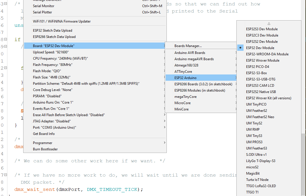
That looks very similar to what i have, i select 'ESP32 Devkit" (4th from the top) and the example works for me.
That may be confusing, but you can define the ESP32 as you like. Pins 17 & 16 are the default pins for UART2, but as long as you don't have any conflicts you could and define them as the Rx & Tx pins for UART2 (or UART1 even if you want, but then there is no pins connected to the USB to TTL converter.
You can change this line to
dmx_port_t dmxPort = 2;
if you want but it won't make any difference.
It works for me, i don't know what else to tell you. Any chance there is anything wrong with the connections ?
How about manually setting the direction pin by just pulling it up ?
And do make sure that you have selected the proper board.
This is the board i have
Yea, I don't know what is going on.
The board certainly works using the processor I select in the boards menu - I use this board for a lot of other projects.
The direction pin is already tied high (transmit) to eliminate that issue.
Quite a lot of time has now gone into this.... so maybe I need to admit defeat!
A lot of things may not be as processor specific as the direct UART control of the esp-dmx library.
During one of my experiments with this library and being short on pins, i once selected one of the input-only pins as the direction pin, and that stopped the output from working.
Just to be clesr i actually have this working using 2 different UARTs for input and output and all works for me. (there was no point for trying them at the same time but even that i think works)
So much time into this sort of stuff anyway, but if you want to drop it, that's up to you.
I haven't checked the gitbub page at all, and it probably has been raised as an issue, but if not, i guess it should be done. Authors do tend to get around to fixing these sort of things eventually.
My issue is the resistor supplying the opto isolator.... I am sure of it
I have 6n137. What resistor value would you use to connect this to the Serial out of the ESP32? (bearing in mind it's 3.3v).
I thought 330r, but this results in the light flickering. Higher (470r) doesn't work at all.
I dropped it to 220r.... nope. Tried 150r and now I think the opto-isolator is dead.
I thought I did the led maths correctly.... clearly not
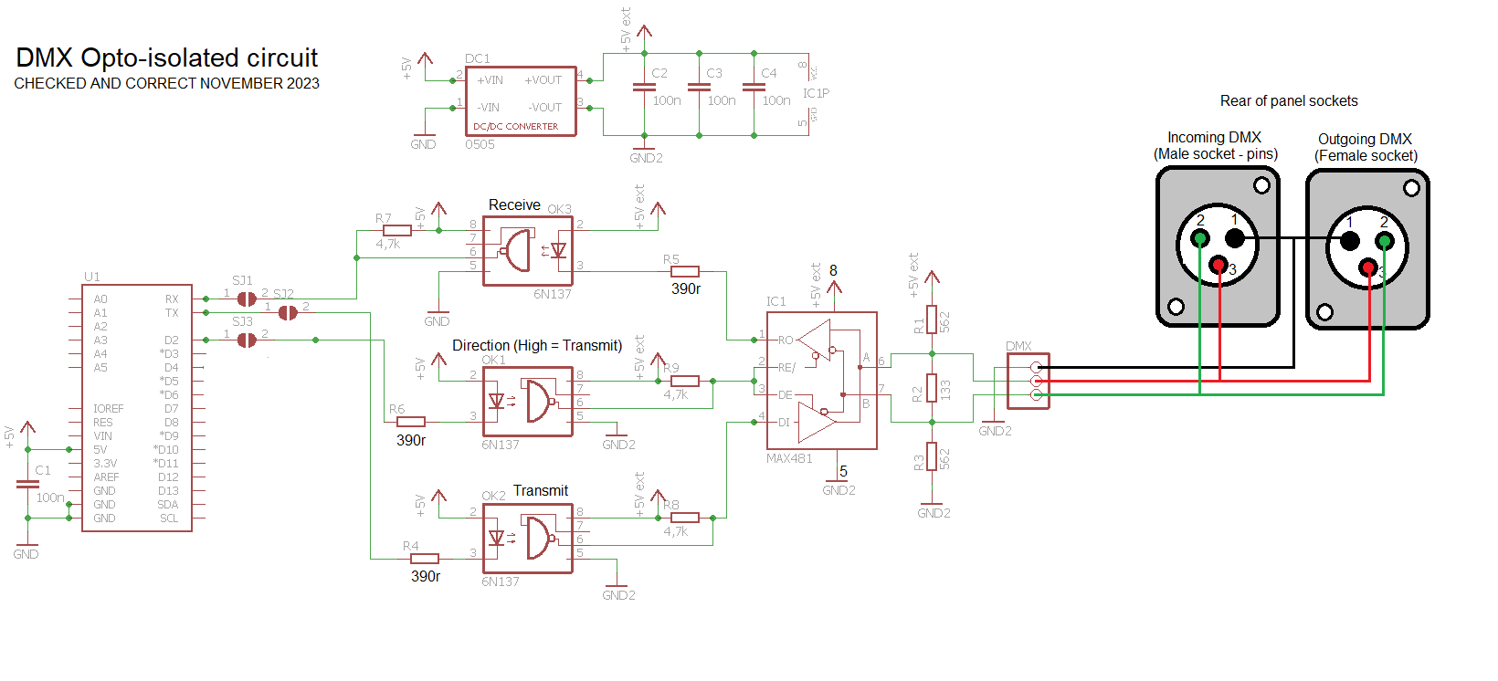
This is a screenshot of my DMX in and DMX out circuit for a 3.3v device (an ESP32 in this case, but all should work the same)
The MAX485 on the left drives DMX-out and is constantly in output mode
The one the Right is used for input and can be switched.
The pin numbers of the screw-terminal for the output are also pin numbers of the XLR-plug for the DMX cable.
Both Max485's are powered with 5v and the Voltage divider on the input reduces the logic level down to a safe 3.3v
Note the absence of a GND connection to the cable on the input side.
If it works with a teensy, it should work with an ESP32. They are both 3.3v devices. There must be another cause. Could it be just lack of 5v current supply ?
I found what I thought was the cause this morning. I stupidly added a LED to tell me when the direction signal was high. This was holding the direction opto-isolator in an odd state.
Replaced the opto-isolators and deleted the led I thought we were going to be sorted...... nope.
I have used this circuit before with no problems. I just can't see what the issue is.
Not working on ESP32 or Teensy.
Has its own clean 5v supply.
DMX light is def working, as I have a DMX tester here and that works it fine.
My test code for the light using a Teensy 4.1 is:
#include <TeensyDMX.h>

namespace teensydmx = ::qindesign::teensydmx;

// Pin for enabling or disabling the transmitter.
// This may not be needed for your hardware.
constexpr uint8_t kTXPin = 2;

// Create the DMX sender on Serial1.
teensydmx::Sender dmxTx{Serial7};

// Data for 3 channels.
uint8_t data[3]{0x44, 0x88, 0xcc};

void setup() {
  // Turn on the LED, for indicating activity
  pinMode(LED_BUILTIN, OUTPUT);
  digitalWriteFast(LED_BUILTIN, HIGH);

  // Set the pin that enables the transmitter; may not be needed
  pinMode(kTXPin, OUTPUT);
  digitalWriteFast(kTXPin, HIGH);

  // Set some channel values. These are being set in setup() to
  // illustrate that values are 'sticky'. They stay set until changed.
  // There's no special function to call for each iteration of loop().

  // Set channel 1 to 128
  dmxTx.set(1, 255);    // Brightness full
  dmxTx.set(2, 255);    // Red full
  dmxTx.set(3, 0);        // Green off
  dmxTx.set(4, 0);        // Blue off

  // Set channels 10-12 to the 3 values in 'data'
  //dmxTx.set(10, data, 3);

  // Call this after setting up the channel contents if you want to
  // guarantee that the values are used as the initial contents;
  // transmission doesn't start until after begin() is called.
  // If it doesn't matter, begin() can be called before setting the
  // channel contents.
  dmxTx.begin();
}

void loop() {

}
I have currently got 220r resistors in for R4 and R6. Still nothing at all.
Could it be these need to be 100r? The isolators appear to work, so surely that means the 220r is doing it's job?
If I put GND on the transmit line, the output pin 6 of the 6n137 which is being held high by the 4k7 resistor, drops to nearly zero.
Same happens on the transmit Opto-isolator.
Not using the RX side of the circuit.
OK. For reasons I don't understand, the system works when you power the entire DMX system from a 3.3v supply.
This means the DMX 5v/5v isolator is now actually working at 3.3v, so I am going to have to check the specs on that.
I thought the whole system would be fine at 5v still, seeing as the only interaction between the DMX circuit and the Teensy is the Opto-isolator leds.
The DMX circuit before the opto-isolators and the Teensy share a common ground, so why should it matter whether the DMX Isolator is driven from the 5v rail or the 3.3v rail?
Don't get it.
That doesn't make sense at all. The transceiver should be powered from 5v, shouldn't it ? What does the datasheet say. Anyhow since the transceiver basically switches the polarity of the A & B lines for HIGH and LOW logic, the receiving end is probably OK with it (for small home testing ? ) I think the voltage difference between a & B is anyway something in the order of 2.5v..
Also doesn't make sense.
One would say so, but the RX-line is pulled HIGH with 5v, and that is not such a good plan on a 3.3v MCU.
The same goes for the 2 output pins that have to sink 5v - the voltage drop of the opto-isolator. I am sure that side of the module should be powered with 3.3v instead of 5v ! Chances are protective circuits on the ESP32 may start working and disturb the output signal.
If they share a common GND then what is the point of an opto-isolated circuit ?
Anyway, with this in mind, i would disconnect the RX line.
I would also select an alternative pair of GPIO pins in the ESP sketch and use that. It is an option and you may have even damaged the pins you used, though probably not.
Personally i would not have both an input and an output socket connected to the same transceiver, simply because this can cause 2 transceivers to be in output mode at the same time. 1 DMX master go into input mode for RDM communications, but i would not connect another Master to it. I that case i would always use 2 transceivers.
About the configuration of the Pullup-Terminator-Pulldown resistors on the transceiver twisted pair, that is probably a bit transceiver dependant, and with short lines and few devices it probably won't matter much, but in bigger setups this will require more testing.
I mainly built DMX-slaves and you don't want terminators on every device, just the one per chain at the very end, and the one on the master is really only there for RDM.