hello everyone,
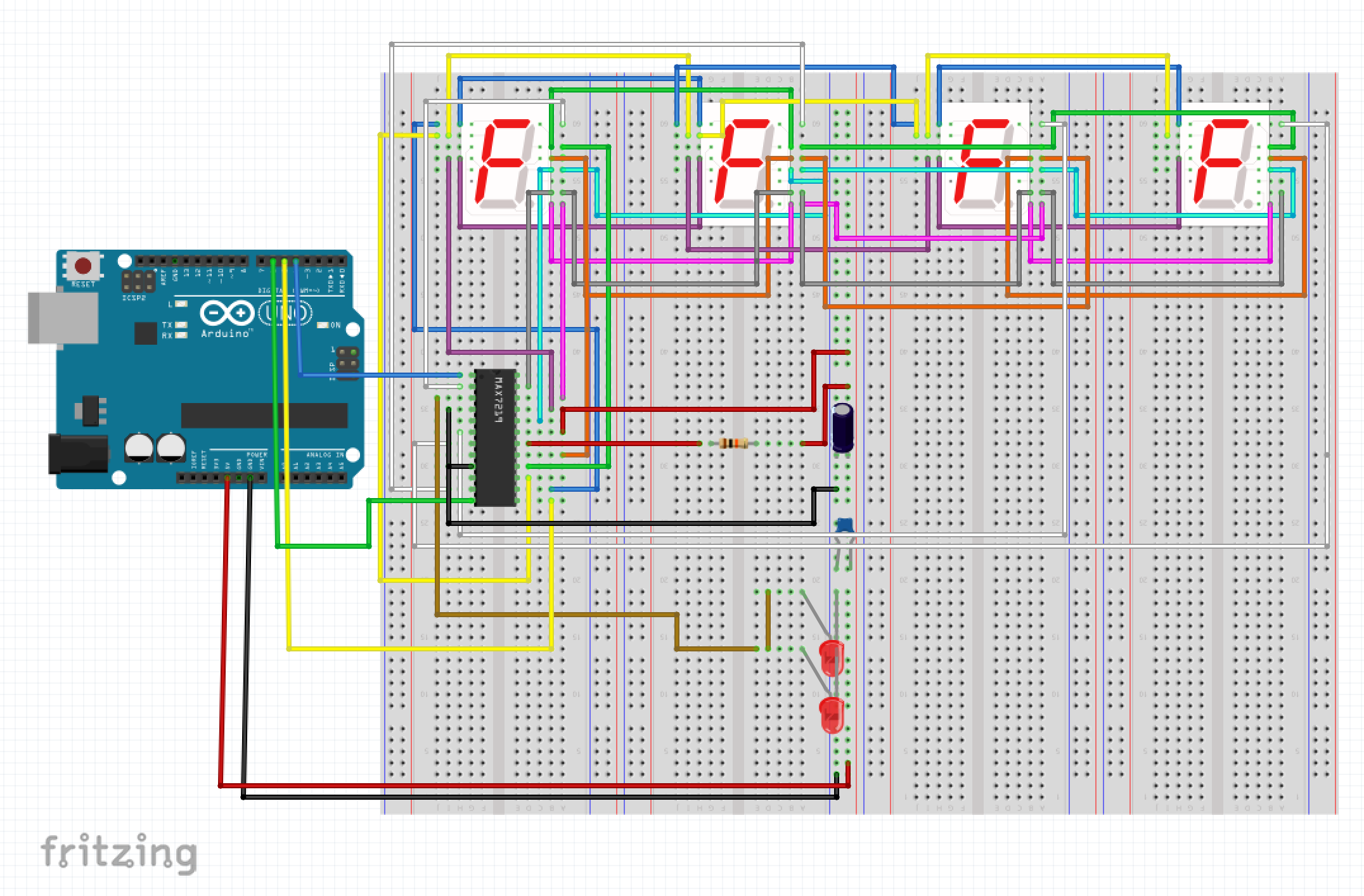
i'm a complete beginner on arduino, and I was trying to make a clock with 4 single digit 7 segment display with common anode with, a tiny RTC module and a 74HC595. I did it like this:

After coding several hours all I can get is 4 "zero" displayed on the 7 segments displays and the 2 LEDs correctly flicking. Here is my code:
// Date and time functions using a DS1307 RTC connected via I2C and Wire lib
#include <Wire.h>
#include <RTClib.h>

// set shift register pins
#define data_pin 13
#define latch_pin 12
#define clock_pin 11

// set digit segments 5V pins
#define d1_pin 1
#define d2_pin 2
#define d3_pin 3
#define d4_pin 4
#define dot_pin 7

#define rotation_cycles 6 // set number of rotation cycles per digit in 'rotation' effect mode
#define mux_delay 3 // set delay between switching display of digits
#define num_digits 10

// define digits, 0 - on, 1 - off
byte segments[10] = {
  0b00000001, // 0
  0b01100111, // 1
  0b00010010, // 2
  0b01000010, // 3
  0b01100100, // 4
  0b01001000, // 5
  0b00001000, // 6
  0b01100011, // 7
  0b00000000, // 8
  0b01000000  // 9
};

byte segments_off = 0b01111111;

// set variables that will keep previous values for minutes and hours to be compared with current values at next run
int prev_minutes = 0;
int prev_hours = 0;
int max_cycles = rotation_cycles * num_digits - 1;
int cycles_remaining = max_cycles; // variable to count remaining cycles for 'rotation' effect
int mod_digit = 0; // digit to be modified during 'rotation'
boolean hide_first_hour = false; // tell the display function whether to show or hide leading zero for hours
boolean first_run = true;
// variables indicating which digit changed
boolean m1_change = false;
boolean h2_change = false;
boolean h1_change = false;

// create RTC object for clock
RTC_DS1307 RTC;


// HELPER FUNCTIONS

// clears digits on display by turning power off
void clearDisplay() {
  digitalWrite(d1_pin, LOW);
  digitalWrite(d2_pin, LOW);
  digitalWrite(d3_pin, LOW);
  digitalWrite(d4_pin, LOW);
}

// display single digit
void displayDigit(int digit_pin, int number) {
  // using shift register to light up required led segments
  digitalWrite(latch_pin, LOW);
  shiftOut(data_pin, clock_pin, LSBFIRST, segments[number]);
  digitalWrite(latch_pin, HIGH);
  // blank display
  clearDisplay();
  // light up required digit
  digitalWrite(digit_pin, HIGH);
}

// display time
void displayTime(int hours, int minutes) {
  int h1, h2, m1, m2;
  h2 = hours % 10;
  h1 = ((hours % 100) - h1) / 10;
  m2 = minutes % 10;
  m1 = ((minutes % 100) - m1) / 10;

  if (hide_first_hour == true) {
    clearDisplay(); // diplay first hour digit only if it is greater than 0
  }
  else
  {
    displayDigit(d1_pin, h1);
  }
  delay(mux_delay);
  displayDigit(d2_pin, h2);
  delay(mux_delay);
  displayDigit(d3_pin, m1);
  delay(mux_delay);
  displayDigit(d4_pin, m2);
  delay(mux_delay);
}

// blink dot
void blinkDot(int seconds) {
  if ( (seconds % 2) == 0 ) {
    clearDisplay();
    digitalWrite(latch_pin, LOW);
    shiftOut(data_pin, clock_pin, LSBFIRST, segments_off);
    digitalWrite(latch_pin, HIGH);
    digitalWrite(d2_pin, HIGH);
    digitalWrite(dot_pin, LOW);
  } else {
    clearDisplay();
    digitalWrite(dot_pin, HIGH);
  }
  delay(mux_delay);
}

// modify single digit for 'rotation' effect
int modifyDigit(int digit) {
  // int cycle = (cycles_remaining - (cycles_remaining % num_digits)) / rotation_cycles;
  int cycle = cycles_remaining / rotation_cycles;
  digit += (num_digits-cycle-1);
  digit %= 10;

  return digit;
}

// modify time for 'rotation' effect
void modifyTime(int *time2display) {

  int h2 = time2display[0] % 10;
  int h1 = int(time2display[0] / 10);
  int m2 = time2display[1] % 10;
  int m1 = int(time2display[1] / 10);

  // modify digit whose turn it is as determined by mod_digit
  switch (mod_digit) {
  case 4:
    m2 = modifyDigit(m2);
    break;
  case 3:
    m1_change = false;
    m1 = modifyDigit(m1);
    break;
  case 2:
    h2_change = false;
    h2 = modifyDigit(h2);
    break;
  case 1:
    h1_change = false;
    h1 = modifyDigit(h1);
    break;
  default:
    break;
  }

  // keep higher digits from changing while lower digits 'rotate' by reducing them by one
  if (mod_digit != 0) {
    if (m1_change == true) {
      m1 = (m1 + 10 - 1) % 10; // add ten before reducing by one to avoid going negative, then get remainder to avoid number higher than ten
      m1 = min(m1, 5); // higher minute digit cannot be greater than 5
    }
    if (h2_change == true) {
      h2 = (h2 + 10 - 1) % 10;
      // set h2 to 2 instead of 9 at midnight
      if (h1_change && h1==0) {
        h2 = min(h2, 2);
      }
    }
    if (h1_change == true) {
      h1 = (h1 + 10 - 1) % 10;
      h1 = min(h1, 2); // higher hour digit cannot be greater than 2
    }
  }

  m2 %= 10;
  m1 %= 10;
  h2 %= 10;
  h1 %= 10;

  // modify time array directly as it was passed to this function by reference - nothing to return
  time2display[0] = h1*10 + h2;
  time2display[1] = m1*10 + m2;
}


// MAIN PROGRAM BODY

void setup() {

  // set pin modes
  pinMode(data_pin, OUTPUT);
  pinMode(latch_pin, OUTPUT);
  pinMode(clock_pin, OUTPUT);
  pinMode(d1_pin, OUTPUT);
  pinMode(d2_pin, OUTPUT);
  pinMode(d3_pin, OUTPUT);
  pinMode(d4_pin, OUTPUT);
  pinMode(dot_pin, OUTPUT);

  // start connection with clock and the clock itself
  Wire.begin();
  RTC.begin();

  // set the clock to current system time - uncomment when need to set time then comment again
  RTC.adjust(DateTime(__DATE__, __TIME__));
}

void loop() {

  // read time
  DateTime now = RTC.now();
  int hours = now.hour();
  int minutes = now.minute();
  int seconds = now.second();
  int days = now.day();
  int months = now.month();
  int hours2display, minutes2display;

  // check if any of time digits (except lower minutes) changed and if yes mark them as subjected to correction during 'rotation'
  if ( ( int(minutes/10) != int(prev_minutes)/10 ) && !first_run ) {
    m1_change = true;
  }
  if ( ( (hours % 10) != (prev_hours % 10) ) && !first_run ) {
    h2_change = true;
  }
  if ( ( int(hours/10) != int(prev_hours)/10 ) && !first_run ) {
    h1_change = true;
  }

  // determine whether to hide or display leading hour digit
  if (hours < 10) {
    hide_first_hour = true;
  }
  else if (hours == 10 && h1_change == true) {
    hide_first_hour = true;
  }
  else
  {
    hide_first_hour = false;
  }

    // display time
    displayTime(hours2display, minutes2display);
    blinkDot(seconds); // blink divider dot
  }
I was thinking that this was due to a problem on the RTC, but when I deplug it, LEDs stop flicking, so I assume that this part of code is right, but I really don't understand why it dosen't show anything else than 4 zeros.
I really tried everything I could, but I have no solution, that's why i'm posting here today ![]()
Anyone got any advice?
Cheers!
Alex
P.S. This is the tiny RTC module i have. Do I have to place a PNP component on it ?
Thanks for answer.