Hey, guys. The thing is that the tp4056 of mine is used for charging the 3.7V battery.
The blocks be like
TP4056 -> XL6009 boost converter -> ESP32
But for some reason the tp4056 is not giving the battery output why is there any flow
And sometime the output voltage is coming and some times not why it show 0.6V
Int out + and out - please help me
There are a lot of posts here about that. Some are correct some not so much. Read a dozen or so of them to get a feel for who knows what. Depending on what you are doing (no code or wiring diagram so hard to know) you may need a few more IC's.
Which one would that be. There are two main types of TP4056 boards.
The ones with and the ones without protection.
The ones with protection have two more chips on the board.
The protection works like a fuse, switching the output off when you draw too much current.
So could your circuit be drawing more than 3Amp.
Leo..
I haven't seen many but I have seen some there wasn't the problem I have it seems,
They goes like
Whenever I turn on, it is a low voltage
But for me,
Some time works well, some time not
I am having the one with protection and two More chip in it
I am using esp32 and lora module as a load does it crave that much current I don't think so

I don't think this might help but when the output goes low, I thought that the area of contact is not enough and scrap some area around and add more contact with the pin but surprisingly it work but for sometime and it continues the same issue
Hi, @jana_muralidharan
Welcome to the forum.
Can you please post a copy of your circuit, a picture of a hand drawn circuit in jpg, png?
Hand drawn and photographed is perfectly acceptable.
Please include ALL hardware, power supplies, component names and pin labels.
This will help immensely.
What is your power source?
Thanks.. Tom.... ![]()
![]()
![]()
![]()

If you don't have the wires soldered, then that is your problem.
But I checked the connectivity it is perfect
Nothing is ever perfect.
The resistance of you poor connections can change resistance when current flows through them.
Twisting wires through the holes or just poking pins through the holes rarely works.
Hi, @jana_muralidharan
What output is your boost converter set too?
Why not set the boost converter to 5V output and leave the LM7805 regulator out?
Do you have a DMM? Digital MultiMeter?
Tom.... ![]()
![]()
![]()
![]()
I thought up on reduction of the voltage in the battery will affect the output like when it goes to 3.4 or 3.2 it will reflect in the output of the boost converter.
But while writting this reply will it really reflect in the output of the boost converter as I am thinking
Yeah
You are right in this thing I agree with that
Will thin wire will reduce voltage? This query is not related to this problem but I am asking will it happened.
But I am soldered the pin with lot of solder
I have a doubt that does having thin track will increase the current to the load and shut the output off with the over current or over discharge protection
Yes. The thinner the wire, the higher the resistance and so the larger the voltage drop across the wire.
But I am soldered the pin with lot of solder
A good solder joint should not require a lot of solder. You may have what is called a "cold solder joint". It look OK but the actual connection is very poor.
Did you try to solder to the battery?
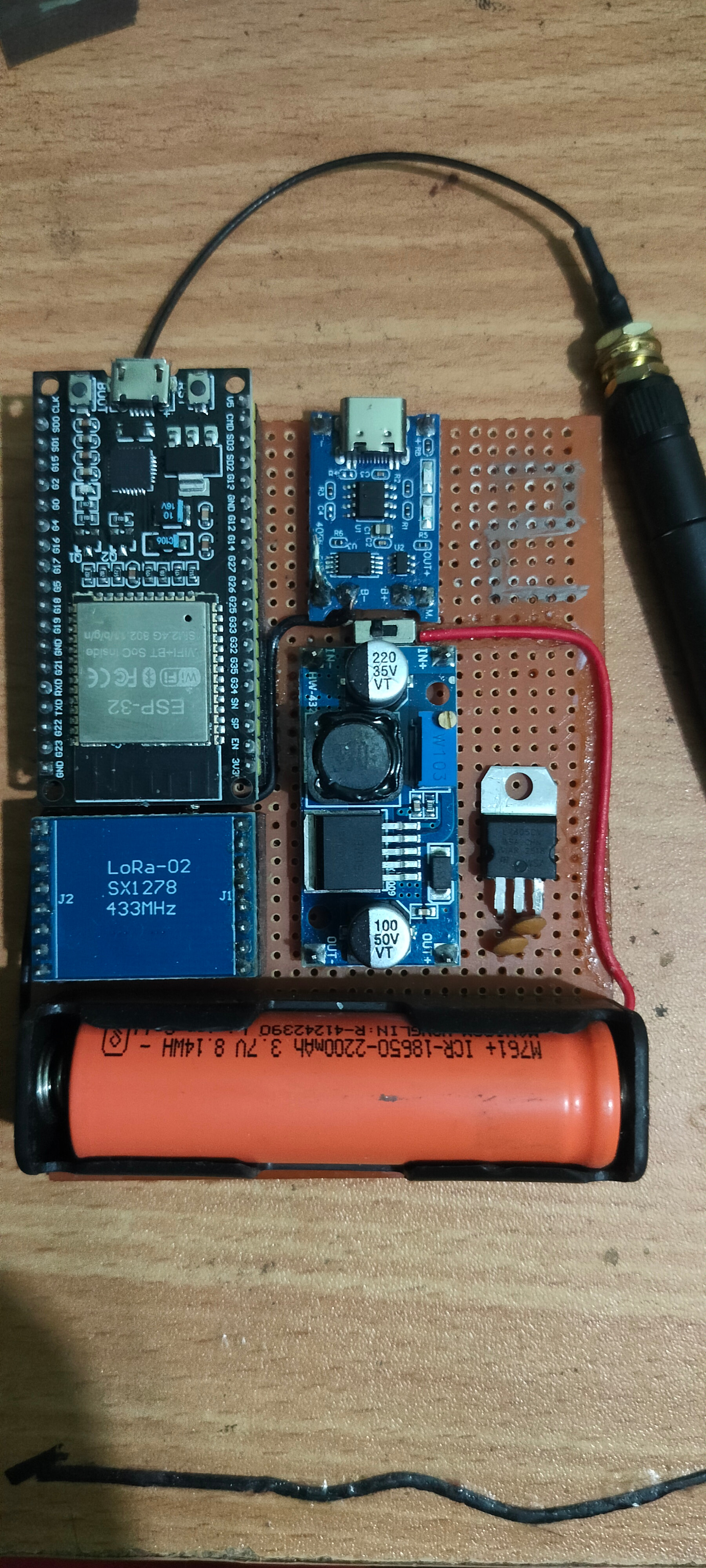
For you guys information, I have implemented the circuit in a pref board

So what is cold solder joint and how to find it


I see a mash-up of parts, not really suitable for long-term battery power (two power-wasting linear regulators and an oversized boost converter).
You should have bought an ESP32 board, designed for battery power.
Then there would have been no need for the TP4056 or buck or 7805.
Leo..
1 Like