I would like to to use external power source for 7-segments, i got 24 of these segments and i will use one TPIC6B595 chip per digit.
I accidentally ordered Common anode segments when i needed common cathode as i planned..
Can i somehow use these CA segments or should i order new segments ?
Check picture, i tried to create circuit for CA but im not sure what im doing so im asking your help.
Just note, i can send serial for CA or CC from my interfacing software.
Hi, and thanks for reply - so my plans looks good ? For my project i cannot multiplex or use any other way to connect 7-segments. Im forced to use one register per Segment.
One shift register per common anode 7-segment display is perfect, no multiplexing needed.
Just shift out the bytes you want to display. Don't forget resistors for each segment.
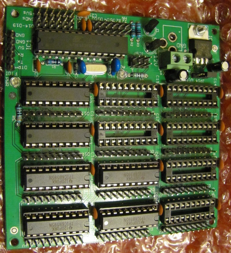
I have a board with a '328P and 12 shift registers to drive 12 digits each if you're interested.
You can have one board send data to the second pretty easily, or leave the processor off the second and daisy chain them to have the one processor send out 24 bytes to be displayed. http://www.crossroadsfencing.com/BobuinoRev17/
CrossRoads:
One shift register per common anode 7-segment display is perfect, no multiplexing needed.
Just shift out the bytes you want to display. Don't forget resistors for each segment.
I have a board with a '328P and 12 shift registers to drive 12 digits each if you're interested.
You can have one board send data to the second pretty easily, or leave the processor off the second and daisy chain them to have the one processor send out 24 bytes to be displayed. Cross Roads Electronics
Connect SCK to all shift registers
Connect SS to all shift registers
Connect MOSI to the first Serial Data In, its Data Out goes to the next part.
You can see that on the board schematic http://www.crossroadsfencing.com/BobuinoRev17/
Connect SCK to all shift registers
Connect SS to all shift registers
Connect MOSI to the first Serial Data In, its Data Out goes to the next part.
You can see that on the board schematic Cross Roads Electronics
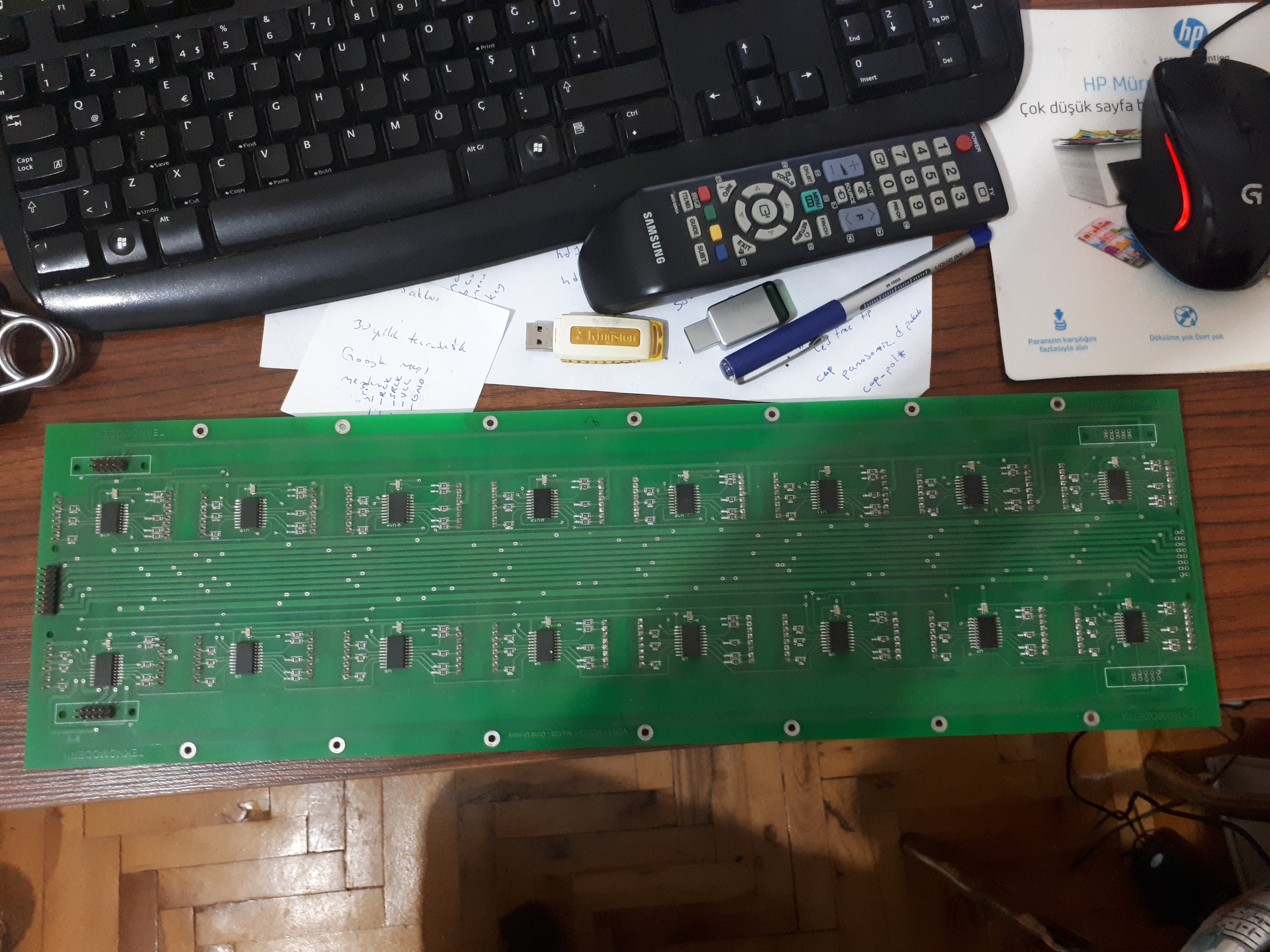
Fabulous, what im looking for thank you. i have dot matrix (8*8) there is a name on themLNM2088AU 010510 coudnt find any data sheet maybe C.cathode and on pcb s.regs. same as your design its old board with 2 pcss, each board 16 dot matrix nad total 32 im gonna try to run with arduino but i need to reverse it about 2 days which pin is which and gonna make custom power sup for it refencre your design, images:
Hi. It would be simple if you could "INVERT" the register holding the data to be outputted. I haven't tryed this on "byte-level".
I'll do this wery often with my programs, but I usually do it on a "bit-level".
Try something like this with the register holding your data:
(output_ data = !output_data) the excl. "!" stands for NOT.