Tri-state amplifier

Anyone have a simple circuit that can amplify voltage and current from a single I/O pin? Take a look at the example schematic for example. The I/O pin can be HIGH, LOW, or High-Z.

If I use an H-bridge configuration (left side), I would need that to correspond to 12V/0V for a HIGH input, 0V/12V for a LOW input, and effectively open-circuit on either or both sides for high-Z. The parts count gets excessive with all the driver circuits I come up with. No good.

I've also considered using a single-ended driver (right side), where the other half is just a 5V supply. I got close with a pair of bipolar drivers. I got H/L input working, but then high-Z ended up turning on both MOSFETs, shorting the supply. Since I'm not trying to make a magic smoke generator, that one's out...

I need a nudge in the right direction. :~

Hi, you want to buffer a tri state output, how are you going to detect that the output is High-Z.
Two output pins would be better, one output is the logic state, Hi or Low, the other High-Z on or off.
The High-Z pin connects or disconnects all the gate inputs, which have pull down to source resistors fitted.

What happens when you disable a motor drive shield, aren't all the H-bridge switches OFF, hence High-Z?
Any protection diodes fitted would just prevent any voltage applied to the output in High-Z state from going above Supply and below Ground plus diode voltage drop.

Tom... :slight_smile:
ps hope it makes sense, just had our first days of summer and damn aircon not performing.

low side logic level MOSFET with a moderate gate to ground resistance.

TomGeorge:
Hi, you want to buffer a tri state output, how are you going to detect that the output is High-Z.

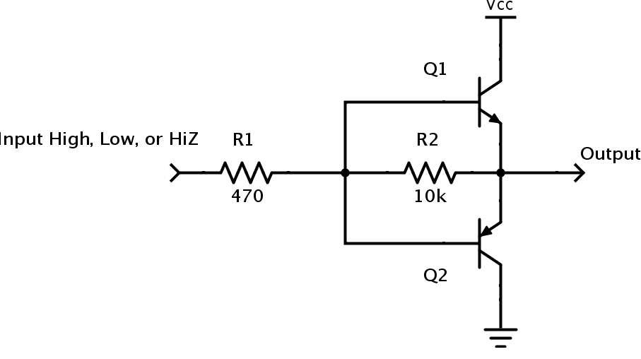
Exactly my question. It seems like there ought to be a way using bipolar transistors for the driver circuit. When the pin is High-Z, there would be no base current flowing, so the bipolar would be in the "off" state. Using a pair of bipolars (one triggered by logic HIGH, the other LOW), it would be possible to have three states -- HIGH = NPN on; LOW = PNP on; High-Z = neither on. Unfortunately, I haven't yet been clever enough to work out an arrangement where this doesn't leave both MOSFETS enabled when the driver BJTs are both off ... mostly thanks to the fact that BJTs inconveniently conduct in ways other than intended for the application.

TomGeorge:
Two output pins would be better, one output is the logic state, Hi or Low, the other High-Z on or off.

For sure, yes. However, it would also be a design well within my capabilities, and I wouldn't have posted the question if that were an option. :wink: BTW, this is an academic question that also has an immediate practical use in a design I'm working on. I'm using an ATmega 1284 and still managed to run out of pins. I do have other options -- shift registers, using 4-bit LCD I/O, or hooking things up to the ICSP pins -- which I'm trying to avoid here. It just struck me as an interesting puzzle that would be helpful to solve, but I managed to drain a laptop battery and get through three episodes of Eureka while trying to come up with something that simulated correctly, and ultimately still failed to do so.

TomGeorge:
What happens when you disable a motor drive shield, aren't all the H-bridge switches OFF, hence High-Z?

Not sure -- I've never used one. I seem to remember them taking two pins to drive, but I could be wrong.

123Splat:
low side logic level MOSFET with a moderate gate to ground resistance.

Unless I'm missing something, that would only accomplish a single polarity output. The example schematic uses two LEDs in reverse parallel. (I know, this doesn't show in the screenshot -- the simulator replaces the schematic symbol with a virtual LED lens that lights up.) Basically, this represents a single 2-pin bi-color LED. Logic HIGH should drive the LED green, LOW should drive the LED red, and High-Z should leave the LED off. You can achieve this effect directly from the I/O pin by connecting one leg of the LED to the pin (through a resistor naturally) and the other pin to 1/2 Vcc, then toggle the pin HIGH/LOW, or set it as an input. But then you're limited to the current capacity of the pin. I'm trying to emulate this with a higher-voltage, higher-current supply.

Keep in mind, the question is meant to be a theoretical exercise (with practical application), so suggestions that skirt around the problem domain by using LED driver ICs or whatever don't really solve the puzzle -- they just avoid it. I can think of plenty of alternate solutions, but that's no fun! I really want to come up with a single-pin way of driving this circuit.

Are you trying to boost the current for a Charlieplexing circuit?

How about this?

If the Arduino output is High or Low, the two transistors operate as emitter follower buffers. But if you change the Arduino pin to an Input, it becomes HiZ and both transistors shut off. The 10k resistor ensures that any charge on the bases drains off, keeping both transistors cut off.

polymorph:
How about this?
Scheme-it | Create or Find Schematics and Diagrams | DigiKey

The requested project does not exist or is private.

sn7455 or l293 (7544 has diodes on output, l293 doesn't) have a enable input that i believe turns off both output transistors when disabled. They also have built in levelshifters/drivers.

It should work now. The image is the same thing.

Does embedding work?

polymorph:
It should work now.

It does.

polymorph:
Are you trying to boost the current for a Charlieplexing circuit?

How about this?
http://www.digikey.com/schemeit#kk6

If the Arduino output is High or Low, the two transistors operate as emitter follower buffers. But if you change the Arduino pin to an Input, it becomes HiZ and both transistors shut off. The 10k resistor ensures that any charge on the bases drains off, keeping both transistors cut off.

Yup, that's a nice way to amplify for charlieplexing if you have a volt or so of headroom. The 10k resistor isn't
needed for charlieplexing in practice, and a current limiting resistor is needed on the output (in fact the input
resistor can be omitted in that case).

If you only want to boost the source and not the sink, or vice versa, you can omit one of the transistors and
add a low value (current-limiting) resistor from base to emitter - you get amplification in one direction and
a current limiting resistor in the other, useful for some multiplexing schemes.

Not for charlieplexing, no. Again, I want to emphasize, this is one of those handy solutions to put in my bag of tricks for when I need it. The current application, which brought the problem to my attention, is just to have an LED driver circuit that can handle any reasonable load, with bi-color and "off" support.

For the curious -- the application is an RFID reader (door lock) with an indicator LED on the back of the control PCB (for debug), one or more on the display side (might end up using a few to light up a perimeter around the reader), and maybe one on the other side of the door. That would be too much to drive from the I/O pin directly, but if I can get away with a few cheap transistors, I don't want to go out of my way using LED driver ICs and whatnot for what's supposed to be a simple indicator. If it gets too complicated, it's no longer worth it. The LED is pretty, but gratuitous -- there will already be an LCD display that can convey the necessary information. (Actually, OLED, for extended temperature range. But you get the point.)

In that case bear in mind the lack of rail-to-rail drive with the emitter follower, but
it ought to be adequate for any load that doesn't mind a volt or so missing... For instance
it works charlieplexing LEDs from 5V, but wouldn't handle green/blue/white
LEDs charlieplexed at 3.3V.

Doesn't seem to work for me. When I simulate it (example attached), a LOW input will power the reverse diode (sinking current), but both HIGH input and High-Z fail result in no current. I tried with a 5v supply on the NPN collector as well. Am I doing something wrong?

test.png

SirNickity:
Doesn't seem to work for me. When I simulate it (example attached), a LOW input will power the reverse diode (sinking current), but both HIGH input and High-Z fail result in no current. I tried with a 5v supply on the NPN collector as well. Am I doing something wrong?

Yes, you are trying to power the thing from 12V, it has to be the logic supply, its only a current amp / buffer.

That didn't seem to make any difference in the sim. TBH, I don't use BJTs much. Most of what I do suits MOSFETs better. I'll play around with it and see if I can figure out what's going on.

Odd. It worked in the simulation in SteveSpice, and in LTSpiceIV. It won't work correctly if you load the base with high capacitance. I'd not omit the 10k resistor, it is there to keep both transistors in cutoff, and for general principles I don't like to leave inputs truly floating.

I can post my LTSpice file when I get home. SteveSpice only runs on one set of wetware.

Oh... duh, NM... I found my problem. When I changed the source voltage from 12v to 5v, I forgot to change the voltage on the sink side, so it was still at 5v. Imagine that, no current flowed from a 5v source to a 5v sink. :*

Changing the sink side to 2.5v works of course. This is a good start, but it puts me awful close to the Vf limits, so I really need to adapt this to use a logic-level input and switch 12v. I'll see what I can come up with.

Well, I've officially given up. :roll_eyes: I've decided to use two pins for bi-color LED control. I'm not sure how my 5v switching regulator would feel about being a current sink anyway.

Oh well, maybe in five years I'll have another try!

IF you move the 220 ohm resistor to the other side and connect one sida of it to +5 V the other to LED. From this point add an second 220 ohm resistor to ground.
Now it vill work. Also change 12v to five to the transistors.

Pelle

If you really want a 5V to 12V tri-state amplifier, try the attached schematic. But it seems to me to be overkill for driving 2 LEDs.