I use the pin as output, make it LOW, use the pin as input, and then wait for the pin to go HIGH (which it always does). The delay(10) is to give it time to drag the voltage down.
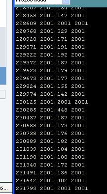
Amazingly, it works. But it only works about 75% of the time. See www.jonbondy.com/ard.jpg, and look at the third column. The counts max out at 2001; anything under that is supposed to be a "contact". This data was taken with my finger firmly on the lead the whole time.
So, the question is where are the spurious 2001 values coming from?
Any ideas? I'm thinking mains hum, but I'm not sure.
When I hold onto the wire, I pull the voltage up. This is what causes some of the values to be less than the maximum of 2001. What puzzles me is why SOMETIME a 2001 pops up. It is as if on occasion my body is unable to pull the voltage up, while it is able to do almost all of the time.
My question has to do with why the values are inconsistent for the same physical situation (finger on the wire the whole time)
Since most of the values are very small, I gather that this approach works, even without the two resistors. I am still puzzled by the fact that it only works MOST of the time.
I cannot read French with enough comprehension to read your article. I did find the original 3D project, but when I tried to read the code, I had to give up. Too much of what was going on used low-level constructs that I could not find, and there were not enough comments to allow me to understand what they were trying to do.
My current approach has the benefit that it requires no resistors. Of course, right now, it only works some of the time.
Since this is so easy to set up (no hardware required at all!), you could try this yourself. The entire LOOP part of my program is:
Jon,
The circuit in the instructables is basically doing the same thing your circuit is doing. In your circuit you are letting the input float high through the internal leakage of the chip. This is a very high impedance and so is subject to all sorts of interference or noise. As you have found this is not repeatable, it's nothing to do with your code it is just the physics of the situation.
When you actually touch the input wire you are changing the coupling into the pin from a purely capacitive coupled injected signal into a resistively coupled injection. This changes the frequency and amplitude of the injected signal and so the system appears, and in fact does, react differently.
Basically your body is acting as a large lump of conducting material that is picking up signals from the air and connecting them to your input control pin. You can observe something similar if you just get hold of an oscilloscope probe. Most of it will be mains pick up at 50 (or 60) Hz but there will be other stuff as well from taxi transmitters, FM radio, to atmospheric thunderstorms the other side of the planet. This is then influencing the charge time of the input pin. The variation you are seeing is caused by the beating between the sample time of your readings and the interference.
The instructables circuit attempts to add a bit more control over this by:-
Having largish capacitive plates for your body to couple to.
Having pull up resistors to increase the current and so shorten the charge time allowing less time for interference to drag it up and down.
Having series resistors to provide a bit of current limiting and filtering on the input.
So basically it works like you see it work, you can't do much to make it more reliable using software because it is fundamentally an unreliable system you have. The instructables circuit is more reliable but only marginally and will work with the same code as you have if you want to try it.