Hey guys I am pretty new with arduino and building circuits and i wanted to try capacitive sensing with it. there is a tutorial for transmit/receive mode based on the Multi Touch Kit Multi-Touch Kit - Human Computer Interaction Lab, Saarland University and it works with every commodity microcontroller while they provide all the code, its basicely plug and play. In the tutorial they say to use this hardware:
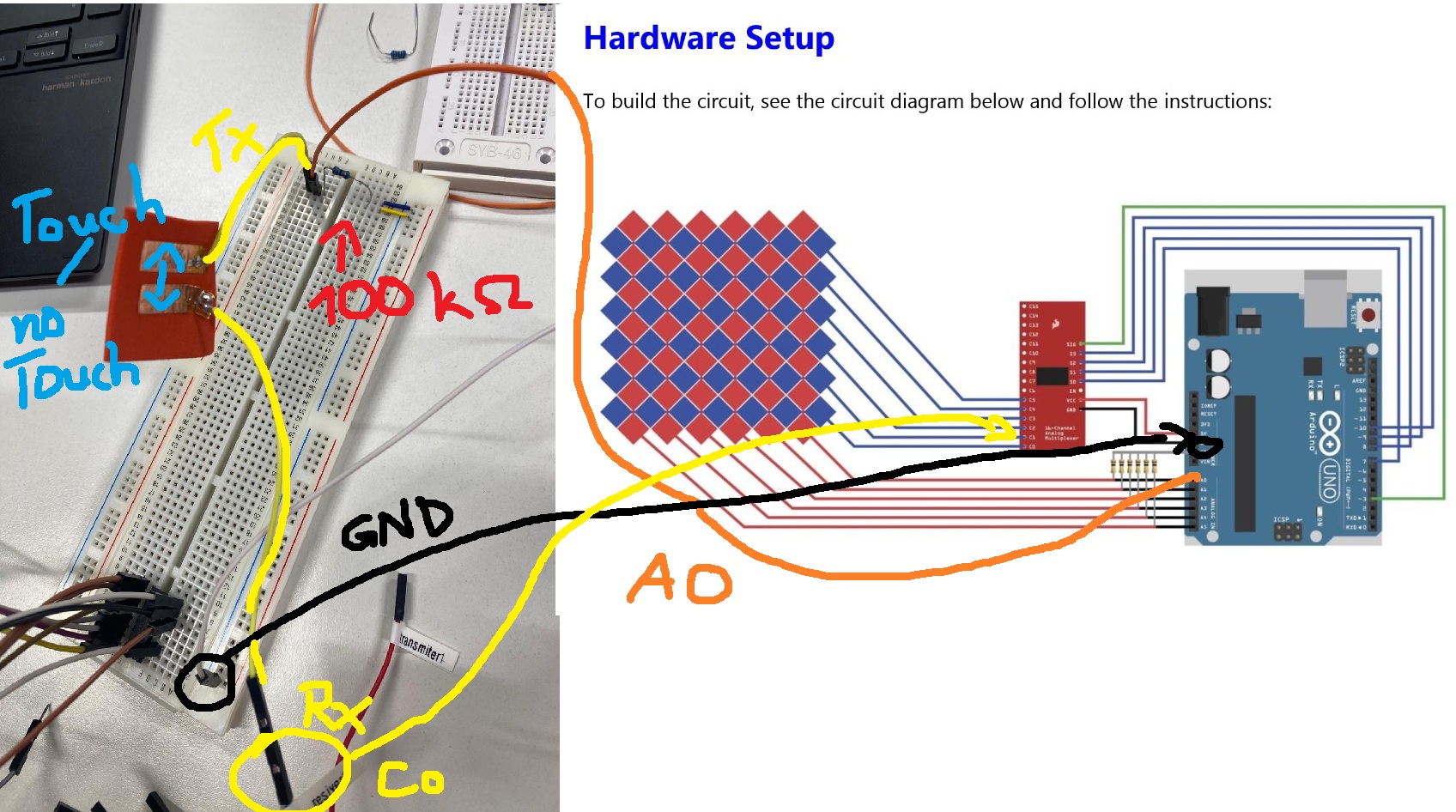
Hardware Setup
– Arduino (Mega2560, Uno, LilyPad)
– Multiplexer (e.g., CD74HC40671)
– Resistors (100K Ohm
for this setup:
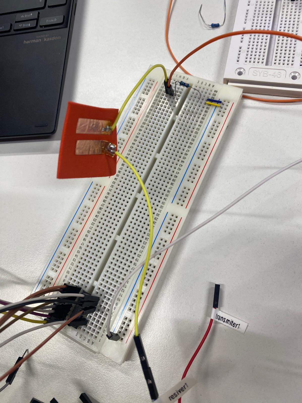
So what i have is an Arduino Uno and they show what to plugin where. I did it exactly like here but first i wanted to test one tx and one rx on the breadboard and i got this 100k resistor (i double checked the farbcodes from resistor); orange cable is conntected to A0, white to GND (ignore the upper multiplexer its from something else). one yellow goes to receivber which is connected to C0 from the Multiplexer CD74HC40671.
In their tutorial there should be a value of around 250 touching electrodes and around 30 at no-touch but i have like peak value of 1023 at no touch so i suppose smth is not well connected?
/***************************************************
 This is a library for the Multi-Touch Kit
 Designed and tested to work with Arduino Uno, MEGA2560, LilyPad(ATmega 328P)
 Note: Please remind to disconnect AREF pin from AVCC on Lilypad

 For details on using this library see the tutorial at:
 ----> https://hci.cs.uni-saarland.de/multi-touch-kit/

 Written by Narjes Pourjafarian, Jan Dickmann, Juergen Steimle (Saarland University),
            Anusha Withana (University of Sydney), Joe Paradiso (MIT)
 MIT license, all text above must be included in any redistribution
 ****************************************************/

 // This example shows how to use the Multi-Touch Kit library with an Arduino Uno/LilyPad and a 6x6 sensor
 // Connect pin 3 on the Uno and pin 9 on the Mega to the Signal pin of the multiplexer
 // Note: Please remind to disconnect AREF pin from AVCC on Lilypad

#include <MultiTouchKit.h>

//----- Multiplexer input pins (for UNO) -----
int s0 = 7;
int s1 = 8;
int s2 = 9;
int s3 = 10;

int muxPins[4] = {s3, s2, s1, s0};

//----- Number of receiver (RX) and transmitter (TX) lines -----
int RX_num = 6;
int TX_num = 6;

//----- Receive raw capacitance data or touch up/down states -----
boolean raw_data = true;  // true: receive raw capacitance data, false: receive touch up/down states
int threshold = 30;  // Threshold for detecting touch down state (only required if raw_data = false).
                    // Change this variable based on your sensor. (for more info. check the tutorial)

MultiTouchKit mtk;

void setup() {
  //Serial connection, make sure to use the same baud rate in the processing sketch
  Serial.begin(115200);

  //setup the Sensor
  mtk.setup_sensor(RX_num,TX_num,muxPins,raw_data,threshold);
}

void loop() {
  //Continuously writes multi-touch data to Serial.
  //Each row represents all RX values read from one TX line seperated by "," (the first value is TX ID)
  mtk.read();
}
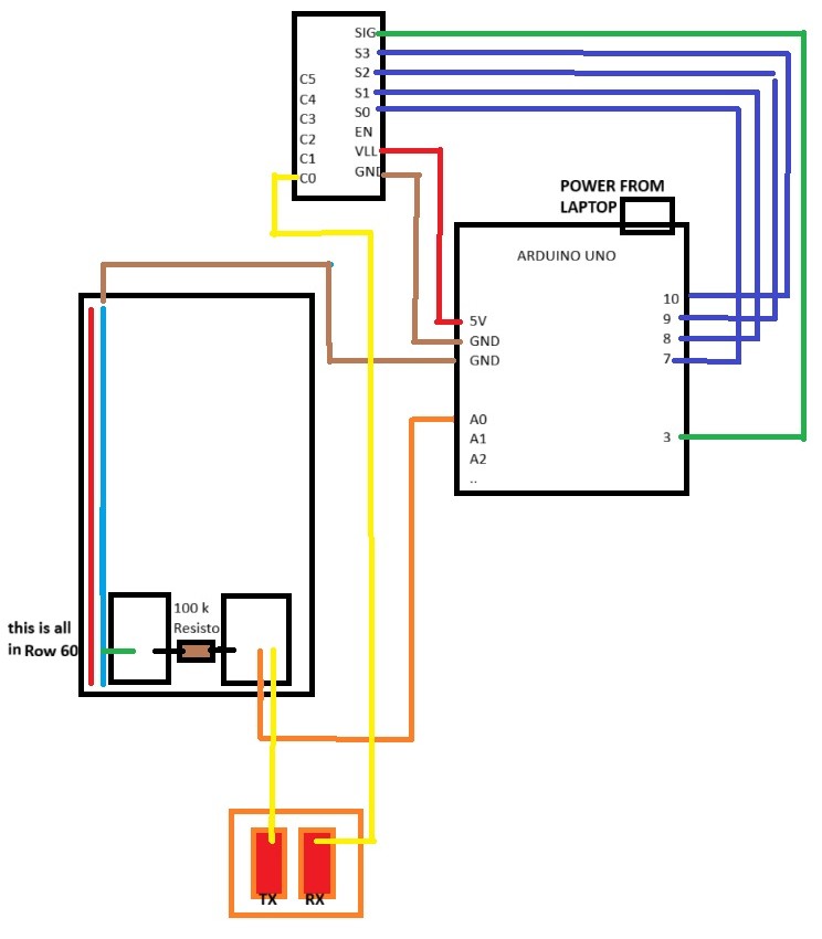
The guide uses a sparkfun breakout board with a HC4067 but it looks like you are using the IC. The IC does not have sig or C0 so exactly how do you have the IC connected?
Can you please post a copy of your circuit, a picture of a hand drawn circuit in jpg, png?
Hand drawn and photographed is perfectly acceptable.
Please include ALL hardware, power supplies, component names and pin labels.
if there is confusion: On the breakboard there can be seen an another multiplexer but that was for something else and it not connected to the Multitouch Project
The MultiTouch Kit provides a finshed code which where you only type how many tx and rx you got. and in the background it uses some code for a transmit/receive mode solution
/***************************************************
 This is a library for the Multi-Touch Kit
 Designed and tested to work with Arduino Uno, MEGA2560, LilyPad(ATmega 328P)
 Note: Please remind to disconnect AREF pin from AVCC on Lilypad

 For details on using this library see the tutorial at:
 ----> https://hci.cs.uni-saarland.de/multi-touch-kit/

 Written by Narjes Pourjafarian, Jan Dickmann, Juergen Steimle (Saarland University),
            Anusha Withana (University of Sydney), Joe Paradiso (MIT)
 MIT license, all text above must be included in any redistribution
 ****************************************************/

 // This example shows how to use the Multi-Touch Kit library with an Arduino Uno/LilyPad and a 6x6 sensor
 // Connect pin 3 on the Uno and pin 9 on the Mega to the Signal pin of the multiplexer
 // Note: Please remind to disconnect AREF pin from AVCC on Lilypad

#include <MultiTouchKit.h>

//----- Multiplexer input pins (for UNO) -----
int s0 = 7;
int s1 = 8;
int s2 = 9;
int s3 = 10;

int muxPins[4] = {s3, s2, s1, s0};

//----- Number of receiver (RX) and transmitter (TX) lines -----
int RX_num = 6;
int TX_num = 6;

//----- Receive raw capacitance data or touch up/down states -----
boolean raw_data = true;  // true: receive raw capacitance data, false: receive touch up/down states
int threshold = 30;  // Threshold for detecting touch down state (only required if raw_data = false).
                    // Change this variable based on your sensor. (for more info. check the tutorial)

MultiTouchKit mtk;

void setup() {
  //Serial connection, make sure to use the same baud rate in the processing sketch
  Serial.begin(115200);

  //setup the Sensor
  mtk.setup_sensor(RX_num,TX_num,muxPins,raw_data,threshold);
}

void loop() {
  //Continuously writes multi-touch data to Serial.
  //Each row represents all RX values read from one TX line seperated by "," (the first value is TX ID)
  mtk.read();
}