Hi there! I am a beginner trying to make a circuit with a photoresistor and a LM35 temperature sensor. Basically, I just want to be able to read an input from one sensor without interference coming from the other sensor.
I wired that up and the temperature values were jumping all over the place.
I tried alternative configurations. Like putting 10k resistors in front of the two sensors but without success. My college course seems far away. I could use some help
Do you use a breadboard, perhaps it has a bad connection.
Do you use long wires ?
The temperature should not jump. Can you tell us what the values are ? with and without the LDR.
When you read an analog input, the 5V is the reference.
If the Arduino board is powered with the USB cable, the 5V might be 4.8V, and your reference is not 5V anymore.
You can avoid that with an external power supply.
Try putting a 1mS delay between each analog read. There is only one analog-to-digital converter in the Atmel chip and the separate analog inputs are multiplexed... It takes a little time for the voltage to "settle". (It shouldn't take 1mS, but that's an easy thing to try.)
DVDdoug:
Try putting a 1mS delay between each analog read. There is only one analog-to-digital converter in the Atmel chip and the separate analog inputs are multiplexed... It takes a little time for the voltage to "settle". (It shouldn't take 1mS, but that's an easy thing to try.)
I already have a 1000ms delay between each read.
I thought the wiring was wrong.
The temperature readings do not jump if i remove the LDR.
Room temperature is about 21.51C. With the LDR readings jump from 15 to 40C
Post a photo of the circuit. The photoresistor output voltage should be constant with no lighting changes.
Make a small cardboard box and poke holes in it. Cover the circuit with the box and observe the values as you punch holes in the box allowing more and more light in. Post or link your code.
Don't worry, we find the cause. Something in plain sight is wrong. I don't know yet if it is the wiring or the sketch.
Please give the full sketch. Are "light" and "temp" float variables ?
And a photo as raschemmel wrote, that shows all the wiring would be very helpful.
Peter_n:
Don't worry, we find the cause. Something in plain sight is wrong. I don't know yet if it is the wiring or the sketch.
Please give the full sketch. Are "light" and "temp" float variables ?
And a photo as raschemmel wrote, that shows all the wiring would be very helpful.
oh sorry I forgot that part of the sketch.
'light' is an integer.
float temp = 0;
int light = 0;
float voltage = 0;

void setup() {
  Serial.begin(9600);

}

void loop() {


  int tempValue = analogRead(A0);
  delay(1000);
  int lightValue = analogRead(A1);
delay(1000);

  temp = tempValue * 0.488759;
  voltage = tempValue;
  light = lightValue;
    Serial.println(temp);
  Serial.println(light);


}
I think the sketch is okay.
Perhaps it is easier to go back one step and also print the integers lightValue and tempValue.
Somehow, you have combined a ground or are using the input of the other one instead the 5V. There is also a very small chance that the analog section of the Arduino board is broken.
Do you have a potentiometer ? If you use that for an analog input, you could test if the values go up and down according to the potentiometer.
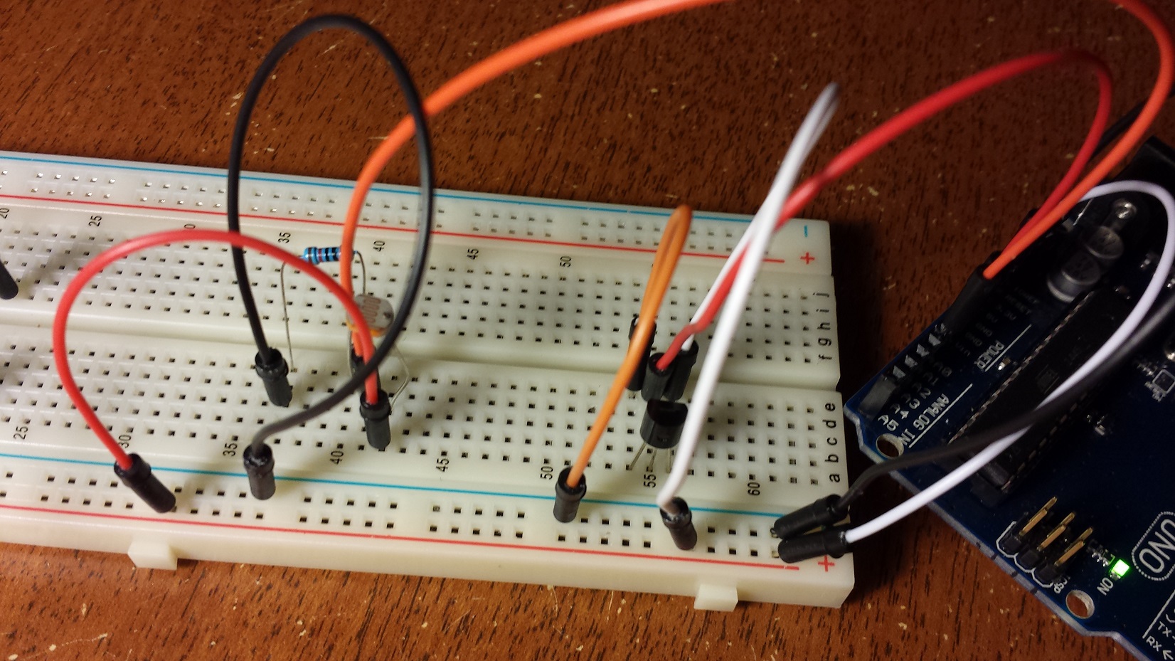
You posted a photo while I was writing this, I will take a look at it now..
The photo seems fine to me. I can't see the GND and 5V pin of the Arduino, but I assume that is okay.
Could you replace the wires from GND and 5V from the Arduino to the breadboard with other wires. Use different holes on the breadboard, and put them in straight down, not with an angle.
If that doesn't help, you need a multimeter to measure if there is 5V on the breadboard.
I swapped the temperature sensor with a 10k potentiometer. All the readings are stable and accurate.
Maybe the sensor is defective.
I read something about the LM35. Someone said that this sensor doesn't like high capacitance or something like that. I have no idea what it meant though. Anyone have a simple answer?
His whole setup is wrong the LM35 needs a pulldown from Vout of 10 to 18K I thought that was what the op was doing at first..
Using the 10k and the LDR to read on A1 and trying to pulldown with the 10K
The LM35 Needs a 10K on the Vout and maybe a small cap there moody little chips.
be80be:
His whole setup is wrong the LM35 needs a pulldown from Vout of 10 to 18K I thought that was what the op was doing at first..
Using the 10k and the LDR to read on A1 and trying to pulldown with the 10K
The LM35 Needs a 10K on the Vout and maybe a small cap there moody little chips.
Nope, that doesn't work either.
Tried with 10k and 20k.
I still don't have capacitors though.
The pulldown resistor is supposed to be between Vout and the input pin right?