We started a project to connect a miniature project with lighting to the Airduino UNO R3.
In this case, we will use 4 digital outputs with addressable LED strips and 4 analog outputs with MOSFETs for individual LEDs.
We've tried some things with Vixen in combination with LED strips on output 6, but the problem now is that when we connect a slightly longer LED strip with the test code, the Airduino often crashes with the sketch code.
We are using 5V LEDs and 12V LEDs. But could it be that the Airduino is defective?
The error message:
Error: cannot set com-state for .COM6
Error: unable to open port COM6 for programmer arduino
Failed uploading: uploading error: exit status 1
I also changed some USB settings as mentioned elsewhere, but it keeps freezing.
Is it possible that we need to connect this differently to the Airduino or put some protections in between?
Not Airduino, but Arduino UNO R3. There is no ' i '.
What is Vixen? Please provide a link to its web page or datasheet. You obviously know what you are talking about, but without context, I have no idea and am just guessing.
How did you interface the 12V LEDs with the Arduino UNO?
The USB settings were mentioned where? They were changed where? And what settings were changed?
The UNO R3 has no analog outputs, only analog inputs. Need more detail on this to understand your design intention. Are you planning on driving the MOSFETS with PWM perhaps and using some form of external (to the UNO) analog conversion?
Please show the sketch code, using the "Copy to forum" feature in the IDE, or the <CODE/> icon at the top of the post editor window. Crashing can be caused by insufficient power to the MCU, e.g. because current drain is too high, among other things, but since we don't have the details of how your project is powered, its difficult to comment.
Please do read the linked article in the above post as it explains why volunteers may need the requested information in order to be able to assist with your problem. Please be aware that we cannot see your project nor how you might have connected things up, or what components or modules you have used unless you give us the details, so please show a schematic or diagram even if hand drawn, and links to documentation or datasheets for the hardware that you are using. It would be helpful to see exactly what we are dealing with.
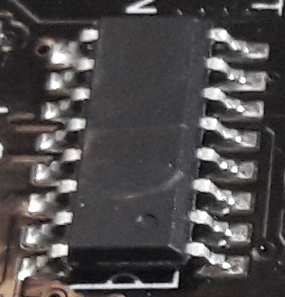
There are some boards on the market that have a USB chip with the same IC package as the WCH CH340, and which are identified by the computer as a CH340. However, these chips don't have the "WCH CH340C ..." labeling like you see on the chip in the picture above:
These mysterious unlabeled chips have different characteristics than the labeled CH340 chips, so please let us know if yours is labeled or not.
If it isn't clear, alternatively you can provide the link to where you bought the board from and we'll see if we can determine the chip from the product listing.
This sounds more like a power/wiring issue than a faulty UNO. Use a separate 5V supply for the LED strips, connect the grounds together, and add a 330–470Ω resistor on the data line plus a capacitor across 5V/GND near the strip. Keep the 12V loads on their own supply/MOSFETs.
The COM6 error can happen when the Arduino resets or USB communication becomes unstable. Try uploading with the LED strips disconnected first—if that works reliably, check the power and wiring before replacing the board.
Thanks for the link. I did find it prior to asking but wasn't sure whether this was what OP was referring to.
I seems to be software that can be used to arrange LED light sequencing. Evidently it is available for Windows only and there is amnetion that is should work with Arduino and a number of other microcontrollers. It also has a web interface and a programming API. However, I see no diagrams showing a typical hardware wiring setup or workflow. The documentation does seem to be written from the point of view of assumed knowledge.
How does Vixen connect with and control the Arduino?
The GPIO pins do need protecting, but we need to see what have so far. How is the lighting hardware interfaced with the UNO GPIOs? Is there some form of pre-built relay or controller board? Or are you designing your circuit board using the MOSFETS you mention? Do you have a design and circuit diagram for your proposed interface?
@sanduwr , as you can see from the all of the above posts and comments so far, we do need a bit more information in order to be able to help you.
Once your Arduino handshaking is solved... I would make small sketches to light each LED, then each WS2812, then add the transistor/mosfet/2308 to light several LEDs... before exploring Vixen.
I have a vague recollection from an earlier topic. (i could look if i can find it since the OP did come to an acceptable solution as far as remember) There is a protocol that sends bytes over Serial
This is what google AI says
The Vixen Generic Serial protocol is a stream-based communication format used by Vixen Lights software to send lighting effect data over a COM port to microcontrollers like Arduino. By default, it operates as a raw sequence of bytes where each byte directly represents the brightness or status of a single output channel (ranging from 00 for completely off to FF for maximum brightness). Because the raw data contains no inherent structural boundaries, the protocol relies heavily on optional, user-defined text headers and footers to keep the receiving hardware synchronized
The Serial protocol feature is one that makes it possible to use an Arduino directly without any other hardware.
I did have it installed at some point but generally it is more off a hobby software package.
With DMX still the standard in clubs and theatres that works using a specification which is RS-485 based (there are some differences ) and it's expansion ArtNet which makes use of UDP packages, generally more used for LED fixtures. The Vixen specific Serial protocol is a bit iffy, and for professional use it isn't all that practical. I don't have more knowledge in my head on the matter. I use those protocols, and DMX can be received easily with a 328P, but one would need a DMX dongle to transmit it from a computer.
ArtNet requires a bit more processing power and an ESP is my MCU of choice for that.
There is quite a bit tutorials / instructables available, If you google 'Arduino vixen' you will find a lot.
First i start with uploading the standard code from Arduino IDE.
void setup() {
  // put your setup code here, to run once:

}

void loop() {
  // put your main code here, to run repeatedly:

}

But i will get the error message:

Error: cannot set com-state for \\.\COM3
Error: unable to open port COM3 for programmer arduino
Failed uploading: uploading error: exit status 1

I tried a different USB port but the message keeps popping up.
I use only the arduino board with an USB cable at this moment, and don't use the LED strips on the board for this moment
.
De Arduino board has power because the light is on.
And the laptop wil 'ping' if i put the USB cable inside.
Probably not use a compatible browser? you need use browser chrome or another browser compatible with web serial! you use windows? anyway in alternative can use a installable serial in your computer ,and try if can connect to your board! because seem that your problem is with connection!