Troubleshooting help for "Simple nRF24L01+ 2.4GHz transceiver demo"

Problem: I cannot successfully execute the "Simple one way transmission" demo code from Post #2 of Simple nRF24L01+ 2.4GHz transceiver demo. The transmit side reads endless lines of "Data Sent Message 0 Tx failed" while the receive side shows only "SimpleRx Starting."
Background: I have been attempting to learn how to use RF transmitters for an upcoming project. I started with DroneBot Workshop's tutorial followed by the How to Mechatronics Tutorial. After a string of failures with the aforementioned tutorials, I found Robin2's "Simple one way transmission" tutorial. After those demo codes failed to yield desirable results, I began further troubleshooting. I have spent the past few weeks pouring over similar forum inquiries and applying the suggestions to my problem. This was to no avail.
Setup:
I am using the NRF24L01+PA+LNA modules with the external antenna and the necessary breakout boards. They are connected to Arduino Unos (1 genuine, 1 clone by ArdiBot) and powered with external 12V power supplies. Both systems are exact copies of each other and one of the setups is pictured below.

Code:
Transmit

// SimpleTx - the master or the transmitter

#include <SPI.h>
#include <nRF24L01.h>
#include <RF24.h>


#define CE_PIN   9
#define CSN_PIN 10

const byte slaveAddress[5] = {'R','x','A','A','A'};


RF24 radio(CE_PIN, CSN_PIN); // Create a Radio

char dataToSend[10] = "Message 0";
char txNum = '0';


unsigned long currentMillis;
unsigned long prevMillis;
unsigned long txIntervalMillis = 1000; // send once per second


void setup() {

    Serial.begin(9600);

    Serial.println("SimpleTx Starting");

    radio.begin();
    //radio.setDataRate( RF24_250KBPS );
    //radio.setDataRate( RF24_1MBPS );
    radio.setRetries(3,5); // delay, count
    radio.openWritingPipe(slaveAddress);
    //radio.setAutoAck(false);
    //radio.setPALevel(RF24_PA_MIN);
}

//====================

void loop() {
    currentMillis = millis();
    if (currentMillis - prevMillis >= txIntervalMillis) {
        send();
        prevMillis = millis();
    }
}

//====================

void send() {

    bool rslt;
    rslt = radio.write( &dataToSend, sizeof(dataToSend) );
        // Always use sizeof() as it gives the size as the number of bytes.
        // For example if dataToSend was an int sizeof() would correctly return 2

    Serial.print("Data Sent ");
    Serial.print(dataToSend);
    if (rslt) {
        Serial.println("  Acknowledge received");
        updateMessage();
    }
    else {
        Serial.println("  Tx failed");
    }
}

//================

void updateMessage() {
        // so you can see that new data is being sent
    txNum += 1;
    if (txNum > '9') {
        txNum = '0';
    }
    dataToSend[8] = txNum;
}

Receive

// SimpleRx - the slave or the receiver

#include <SPI.h>
#include <nRF24L01.h>
#include <RF24.h>

#define CE_PIN   9
#define CSN_PIN 10

const byte thisSlaveAddress[5] = {'R','x','A','A','A'};

RF24 radio(CE_PIN, CSN_PIN);

char dataReceived[10]; // this must match dataToSend in the TX
bool newData = false;

//===========

void setup() {

    Serial.begin(9600);

    Serial.println("SimpleRx Starting");
    radio.begin();
    //radio.setDataRate( RF24_250KBPS );
    //radio.setDataRate( RF24_1MBPS );
    radio.openReadingPipe(1, thisSlaveAddress);
    radio.startListening();
    //radio.setAutoAck(false);
    //radio.setPALevel(RF24_PA_MIN);
}

//=============

void loop() {
    getData();
    showData();
}

//==============

void getData() {
    if ( radio.available() ) {
        radio.read( &dataReceived, sizeof(dataReceived) );
        newData = true;
    }
}

void showData() {
    if (newData == true) {
        Serial.print("Data received ");
        Serial.println(dataReceived);
        newData = false;
    }
}

Serial Monitor:
Transmit

SSimpleTx Starting
Data Sent Message 0  Tx failed

Receive

SimpleRx Starting

Diagnostic Output from CheckConnection.ino

CheckConnection Starting

FIRST WITH THE DEFAULT ADDRESSES after power on
  Note that RF24 does NOT reset when Arduino resets - only when power is removed
  If the numbers are mostly 0x00 or 0xff it means that the Arduino is not
     communicating with the nRF24

SPI Speedz	= 10 Mhz
STATUS		= 0x0e RX_DR=0 TX_DS=0 MAX_RT=0 RX_P_NO=7 TX_FULL=0
RX_ADDR_P0-1	= 0x4141417852 0x65646f4e32
RX_ADDR_P2-5	= 0x33 0xce 0x3e 0xe3
TX_ADDR		= 0x4141417852
RX_PW_P0-6	= 0x20 0x20 0x20 0x20 0x20 0x20
EN_AA		= 0x3f
EN_RXADDR	= 0x03
RF_CH		= 0x4c
RF_SETUP	= 0x03
CONFIG		= 0x0e
DYNPD/FEATURE	= 0x00 0x00
Data Rate	= 1 MBPS
Model		= nRF24L01+
CRC Length	= 16 bits
PA Power	= PA_LOW
ARC		= 5


AND NOW WITH ADDRESS AAAxR  0x41 41 41 78 52   ON P1
 and 250KBPS data rate

SPI Speedz	= 10 Mhz
STATUS		= 0x0e RX_DR=0 TX_DS=0 MAX_RT=0 RX_P_NO=7 TX_FULL=0
RX_ADDR_P0-1	= 0x4141417852 0x4141417852
RX_ADDR_P2-5	= 0x33 0xce 0x3e 0xe3
TX_ADDR		= 0x4141417852
RX_PW_P0-6	= 0x20 0x20 0x20 0x20 0x20 0x20
EN_AA		= 0x3f
EN_RXADDR	= 0x03
RF_CH		= 0x4c
RF_SETUP	= 0x23
CONFIG		= 0x0e
DYNPD/FEATURE	= 0x00 0x00
Data Rate	= 250 KBPS
Model		= nRF24L01+
CRC Length	= 16 bits
PA Power	= PA_LOW
ARC		= 5

Attempted Fixes:

  • using breakout boards instead of direct wiring with a filter capacitor
  • using other nRF24 modules (rotated through 6 total)
  • cutting power to modules after each new upload
  • adjusting power [radio.setPALevel(RF24_PA_MIN))
  • adjusting data rate [radio.setDataRate( RF24_250KBPS ); & radio.setDataRate( RF24_1MBPS ))
  • changing auto acknowledge (radio.setAutoAck(false))

In closing, this is my first post. My apologies in advance for any formatting errors or if I forgot to include anything. Any help is greatly appreciated.

See time 10:29 re miss labeled pins.

Thank you, but I have tried that. The programs still do not function properly. Furthermore, when I run the CheckConnection.ino program it fails.

Maybe faulty modules or wiring then ?

Can you expand on this?
What does the CheckConnection sketch show in the serial monitor?

Swapping the MISO and MOSI pins yields the following result.

CheckConnection Starting

FIRST WITH THE DEFAULT ADDRESSES after power on
  Note that RF24 does NOT reset when Arduino resets - only when power is removed
  If the numbers are mostly 0x00 or 0xff it means that the Arduino is not
     communicating with the nRF24

SPI Speedz	= 10 Mhz
STATUS		= 0xff RX_DR=1 TX_DS=1 MAX_RT=1 RX_P_NO=7 TX_FULL=1
RX_ADDR_P0-1	= 0xffffffffff 0xffffffffff
RX_ADDR_P2-5	= 0xff 0xff 0xff 0xff
TX_ADDR		= 0xffffffffff
RX_PW_P0-6	= 0xff 0xff 0xff 0xff 0xff 0xff
EN_AA		= 0xff
EN_RXADDR	= 0xff
RF_CH		= 0xff
RF_SETUP	= 0xff
CONFIG		= 0xff
DYNPD/FEATURE	= 0xff 0xff
Data Rate	= 1 MBPS
Model		= nRF24L01+
CRC Length	= 16 bits
PA Power	= PA_MAX
ARC		= 15

AND NOW WITH ADDRESS AAAxR  0x41 41 41 78 52   ON P1
 and 250KBPS data rate

SPI Speedz	= 10 Mhz
STATUS		= 0xff RX_DR=1 TX_DS=1 MAX_RT=1 RX_P_NO=7 TX_FULL=1
RX_ADDR_P0-1	= 0xffffffffff 0xffffffffff
RX_ADDR_P2-5	= 0xff 0xff 0xff 0xff
TX_ADDR		= 0xffffffffff
RX_PW_P0-6	= 0xff 0xff 0xff 0xff 0xff 0xff
EN_AA		= 0xff
EN_RXADDR	= 0xff
RF_CH		= 0xff
RF_SETUP	= 0xff
CONFIG		= 0xff
DYNPD/FEATURE	= 0xff 0xff
Data Rate	= 1 MBPS
Model		= nRF24L01+
CRC Length	= 16 bits
PA Power	= PA_MAX
ARC		= 15
  1. I have tested 6 different modules from two different suppliers in both transmit and receive roles. It seems improbable that all units are faulty.
  2. If the wiring was incorrect wouldn't the CheckConnection.ino expose the problem?

Post #6 appears to show that register reads to the NRF24 are all returning 0xFF ..............................

From the printout you posted;

If the numbers are mostly 0x00 or 0xff it means that the Arduino is not
     communicating with the nRF24

There are examples with the library that work , start with those ?

In Post #6, I swapped the MISO and MOSI pins to show that the connection order was not faulty as LarryD suggested in Post #2. Markd833 requested the CheckConnection.ino readouts from the swapped configuration in Post #5. This is what Post #6 is showing.
The original configuration appears to pass CheckConnection.ino. For that one please see Post #1.

I have tried the RadioHead library "nrf24_server" & "nrf24_client" examples and the RF24 library "GettingStarted" example. They have not yielded successful results either. They behave similarly to the "SimpleTx" & "SimpleRx" examples from Robin2's tutorial.

Did I? Swapping MOSI & MISO doesn't appear in this discussion until you mention it in post #6.

Clearly MOSI & MISO were connected the right way round in your initial post.

Did both Arduinos give the same results as shown in the CheckConnection printout in post #1?

I've seen strange results if you have CE & CSN swapped.

Agreed, unless something in your setup is affecting them.

I've not used the nRF24L01 modules for a while, but I seem to recall that there was an update to the library that is used in Robins tutorial. I wonder if reverting back to a slightly older library would help in tracking down the issue(s).

You are powering with 3.3v?

I used something akin to this simple tutorial and they worked first time . Suggest you give it a go .

Here

Don’t forget you have pipes and frequencies to set

I thought that is what you were asking for when you quoted Post #3. In that post I responded to LarryD's suggestion. He cites the Dronedot Workshop Tutorial where it is mentioned that there is a potential problem arising from miss labeled pins on the breakout board (MISO & MOSI). Swapping them has resolved the issue for some. Given LarryD's suggestion was referencing an outside source, I probably should have made it clearer in my reply what solution I was attempting. My apologies.

Of the many times I have used the program, the CheckConnection.ino readouts have always been nearly identical between modules. The only noticeable variation is in the numbers following the "0x" part (i.e. 0x03 to 0x07). Would you like me to post fresh readouts for both?

I am almost certain they are wired correctly. Should I try swapping them and testing them?

I initially started by using version 1.4.6. I have since switched and am currently using version 1.1.7, as was suggested in the tutorial. All tests posted here were conducted using version 1.1.7.

I am using a breakout board with a built-in voltage regulator that converts the 5V supply to 3.3V for the module.

Thank you for the tutorial recommendation. I will give it a try.

I am unsure how to properly do this. Is it set properly in the code of Post #1?

That’s why you need to run that example , then read around the device to see how it works . The device can run at a range of frequencies ( channels ) in the 2.4 band, “pipes “ are further coded routes - Need to be the same at both ends , then it’s just a serial link , providing one is set to send , the other to listen .
I’ve no idea what the program you have is trying to do.
Look at the sparkfun tutorial too .

Here too

I’ve no idea what the program you have is trying to do.

The purpose of the code is to send "Message #" to the receiving end. Then it should verify that the message was received.

I've been going over the code. I believe the frequency is set correctly as they are on the same default channel. I think the pipes are set correctly. The pipes are defined as follows:
Transmit

const byte slaveAddress[5] = {'R','x','A','A','A'};
...
void setup() {
...
    radio.openWritingPipe(slaveAddress);

Receive

const byte thisSlaveAddress[5] = {'R','x','A','A','A'};
...
void setup() {
...
    radio.openReadingPipe(1, thisSlaveAddress);

Does this look correct?

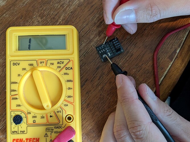
The problem was hardware related. The filter capacitors were not connected to the ground plane on the NRF24L01+ Power Module PCB. This was tested using a multimeter checking for continuity (shown in the picture below).

The points tested were the ground pin of the module and the via, which is supposed to link the top ground plane of the capacitors to the ground pin. The points tested for continuity are shown by the red arrows in the picture below.

The Solution:
Solder a wire between the via and the ground pin.
Before and after pictures are shown below.


Once this is done, check for continuity.


After this modification, the tutorial code should run properly.

This topic was automatically closed 180 days after the last reply. New replies are no longer allowed.