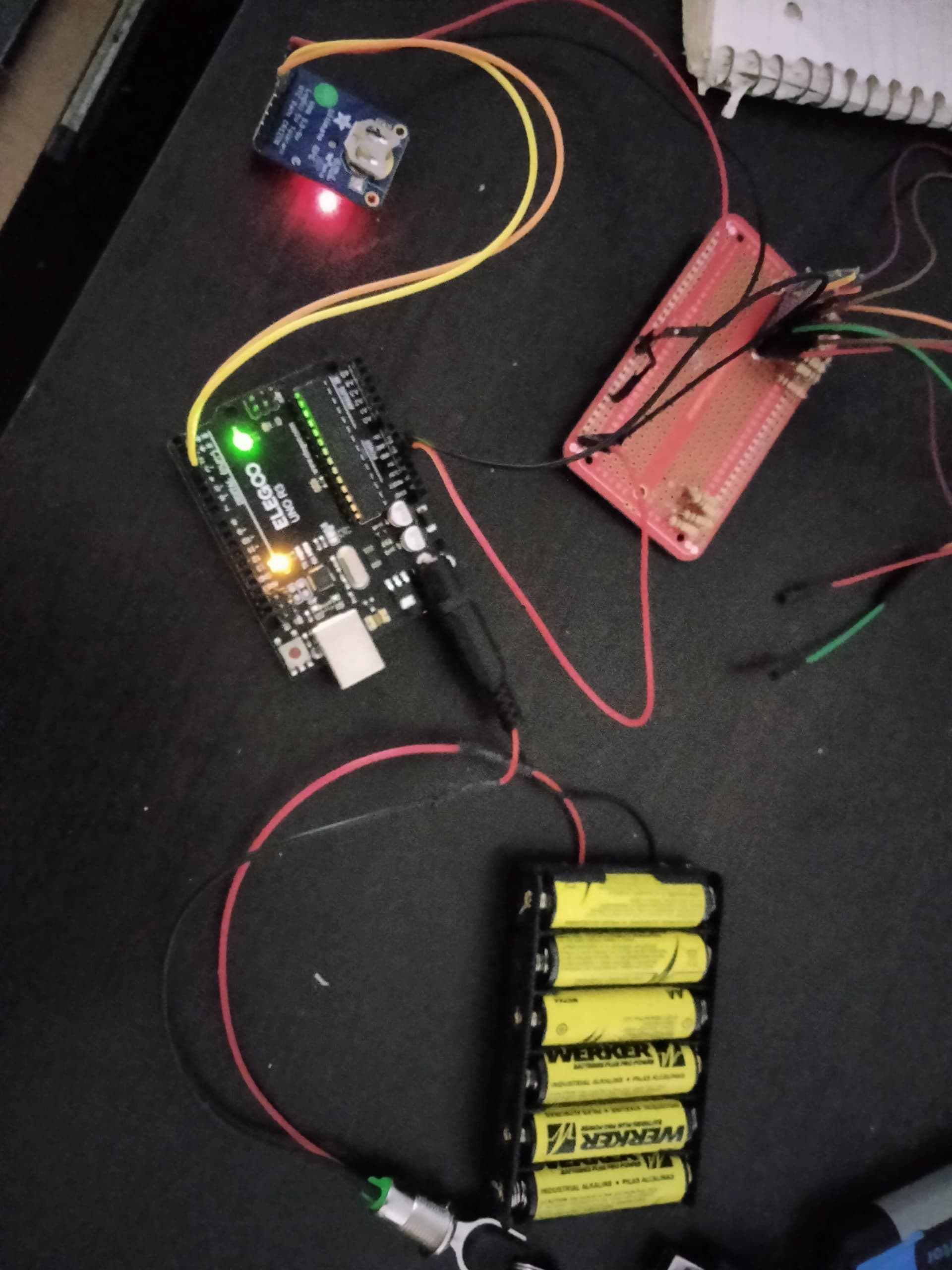
Hello all, I'm having trouble with sending over serial data of a GPS to the arduino using an external power supply. When plugged into the computer with the IDE and code, it works as intended. It just doesn't work with an external power supply since I cannot see the blinking lights indicating work being done. I'll send a rough draft diagram I made as well as the sketch. The whole idea here is for the GPS to generate my data, then the arduino processes and formats the data and send it over to the LCD screen I have.

#include <Adafruit_GPS.h>

// these are for Arduino 1.0
#include <SoftwareSerial.h>
SoftwareSerial mySerial(3, 2);

// if using Arduino v23 or earlier, uncomment these
// two lines and comment out the above. You will
// need to install NewSoftSerial
//  #include <NewSoftSerial.h>
//  NewSoftSerial mySerial(3, 2);

// Set GPSECHO to 'false' to turn off echoing the GPS data to the Serial console
// Set to 'true' if you want to debug and listen to the raw GPS sentences
#define GPSECHO  false

// Connect the GPS Power pin to 5V
// Connect the GPS Ground pin to ground
// Connect the GPS TX (transmit) pin to Digital 3
// Connect the GPS RX (receive) pin to Digital 2
Adafruit_GPS GPS(&mySerial);

// this keeps track of whether we're using the interrupt
// off by default!
boolean usingInterrupt = false;

void setup()
{

  // connect at 115200 so we can read the GPS fast enough and echo without dropping chars
  // also spit it out
  Serial.begin(115200);
  Serial.println("Adafruit GPS library basic test!");
  // 9600 NMEA is the default baud rate for Adafruit MTK GPS's- some use 4800
  GPS.begin(9600);

  // uncomment this line to turn on RMC (recommended minimum) and GGA (fix data) including altitude
  GPS.sendCommand(PMTK_SET_NMEA_OUTPUT_RMCGGA);
  // uncomment this line to turn on only the "minimum recommended" data
  //GPS.sendCommand(PMTK_SET_NMEA_OUTPUT_RMCONLY);
  // For parsing data, we don't suggest using anything but either RMC only or RMC+GGA since
  // the parser doesn't care about other sentences at this time

  // Set the update rate
  GPS.sendCommand(PMTK_SET_NMEA_UPDATE_1HZ);   // 1 Hz update rate
  // For the parsing code to work nicely and have time to sort thru the data, and
  // print it out we don't suggest using anything higher than 1 Hz

  // the nice thing about this code is you can have a timer0 interrupt go off
  // every 1 millisecond, and read data from the GPS for you. that makes the
  // loop code a heck of a lot easier!
  useInterrupt(true);

  delay(1000);
}

// Interrupt is called once a millisecond, looks for any new GPS data, and stores it
SIGNAL(TIMER0_COMPA_vect) {
  char c = GPS.read();
  // if you want to debug, this is a good time to do it!
  if (GPSECHO)
    if (c) UDR0 = c;
    // writing direct to UDR0 is much much faster than Serial.print
    // but only one character can be written at a time.
}

void useInterrupt(boolean v) {
  if (v) {
    // Timer0 is already used for millis() - we'll just interrupt somewhere
    // in the middle and call the "Compare A" function above
    OCR0A = 0xAF;
    TIMSK0 |= _BV(OCIE0A);
    usingInterrupt = true;
  } else {
    // do not call the interrupt function COMPA anymore
    TIMSK0 &= ~_BV(OCIE0A);
    usingInterrupt = false;
  }
}

uint32_t timer = millis();
void loop()                     // run over and over again
{
  // in case you are not using the interrupt above, you'll
  // need to 'hand query' the GPS, not suggested :(
  if (! usingInterrupt) {
    // read data from the GPS in the 'main loop'
    char c = GPS.read();
    // if you want to debug, this is a good time to do it!
    if (GPSECHO)
      if (c) UDR0 = c;
      // writing direct to UDR0 is much much faster than Serial.print
      // but only one character can be written at a time.
  }

  // if a sentence is received, we can check the checksum, parse it...
  if (GPS.newNMEAreceived()) {
    // a tricky thing here is if we print the NMEA sentence, or data
    // we end up not listening and catching other sentences!
    // so be very wary if using OUTPUT_ALLDATA and trytng to print out data
    //Serial.println(GPS.lastNMEA());   // this also sets the newNMEAreceived() flag to false

    if (!GPS.parse(GPS.lastNMEA()))   // this also sets the newNMEAreceived() flag to false
      return;  // we can fail to parse a sentence in which case we should just wait for another
  }

  // if millis() or timer wraps around, we'll just reset it
  if (timer > millis())  timer = millis();

  // approximately every second or so, print out the current stats
  if (millis() - timer > 1000) {
    timer = millis(); // reset the timer
    //****************************************************************************************BEGIN PACKET PRINT ROUTINE***********************************************************
    //Serial.print("\nFIX: ");
    Serial.print("$");//Just a random character I chose as the "qualifying character" that is necessary for the UART on the uLCD43 to begin reading the serial stream into its buffer
    Serial.print(GPS.fix);
//Serial.print("|");
    //Serial.print("TIM: ");
    if (GPS.hour < 10) Serial.print("0");
    Serial.print(GPS.hour, DEC);// Serial.print(':');
    if (GPS.minute < 10) Serial.print("0");
    Serial.print(GPS.minute, DEC);
//Serial.print("|");
    //Serial.print("DAT: ");
    if (GPS.day < 10) Serial.print("0");Serial.print(GPS.day, DEC); //Serial.print(':');
    if (GPS.month < 10) Serial.print("0");Serial.print(GPS.month, DEC); //Serial.print(":");
    Serial.print(GPS.year, DEC);
//Serial.print("|");
    if (GPS.fix) {
    //Serial.print("LAT: ");
    Serial.print(GPS.latitude, 4); Serial.print(GPS.lat);
    //Serial.print("LON: ");
    Serial.print(GPS.longitude, 4); Serial.print(GPS.lon);
//Serial.print("|");
    //Serial.print("SPD: ");
    if (GPS.speed < 10)Serial.print("0");
    if (GPS.speed < 100)Serial.print("0");
    Serial.print(int(GPS.speed));//Serial.println(" KNTS");
//Serial.print("|");
    //Serial.print("ANG: ");//format so that angle is always a 3 character string
    if (GPS.angle < 10)Serial.print("0");
    if (GPS.angle < 100)Serial.print("0");
    Serial.print(int(GPS.angle));//Serial.println(" DEGS");
//Serial.print("|");
    //Serial.print("ALT: ");//format so that altitude is always a 5 character string
    if (GPS.altitude < 10)Serial.print("0");
    if (GPS.altitude < 100)Serial.print("0");
    if (GPS.altitude < 1000)Serial.print("0");
    if (GPS.altitude < 10000)Serial.print("0");
    Serial.print(int(GPS.altitude));//Serial.println(" FT");
//Serial.print("|");
    //Serial.print("TRK: ");
    if (GPS.satellites < 10) Serial.print("0");
    Serial.println(GPS.satellites);//Serial.println(" SATS");
    }
  }
}