I am trying to build some kind of MIDI to CV controller board but i want to have more than the 5 volts that an Arduino like dev board can give. I have elected Arduino Pro micro because is relatively cheap and having direct USB connection support to try making this project ...
In order to have precise voltage output i use two MPC4725 modules, one that outputs slightly less than 5 volts and the other i have connected to the non inverting input of an LM358P that theoreticaly doubles the output up to slightly less than 10 volts, connecting a 7.7K resistor from the opamp's output pin to the inverting input and a second 10K resistance for the same input to the ground. Both MPC4725 modules are sourced from the VCC pin of the Pro Micro board, and connected to the same board ground pin.
When i tried with the Arduino board and the two MPC4725 without the opam, all went good, I2C scanner sketch gave the two modules differentiated address and tried another sketch cycling the output from 0 to 4 volts out of both modules.
Then i decided to disconnect the USB cable and to connect one module's output to the opamp setup but putting a 1000K resistor in between. Then i connected the 12 volts CC regulated power to the circuit, making sure that the 12 volts positive input was on the RAW pin and the negative to the ground pin of the board. And, FSSSSS, i had Smoke On the Water, but not Deep Purple's great song, no, it was a fetid smoky column of frustration!
Previous to this try, i connected all that stuff but being the Pro Micro board connected to the USB plug and the power source's 12volts only to the opamp's VCC pin and ground cable to the VEE pin. Even though the board was not destroyed like the one i mention above the board does not work well, it gets very hot and my computer can not establish connection with it.
I know, I am doing things terrible bad (just like my english hehehe) but I though that i could connect that way...
Can you show a diagram of what you are trying to do please? Both the layout of the original circuit and then what you did to modify it when you added ti op amp.
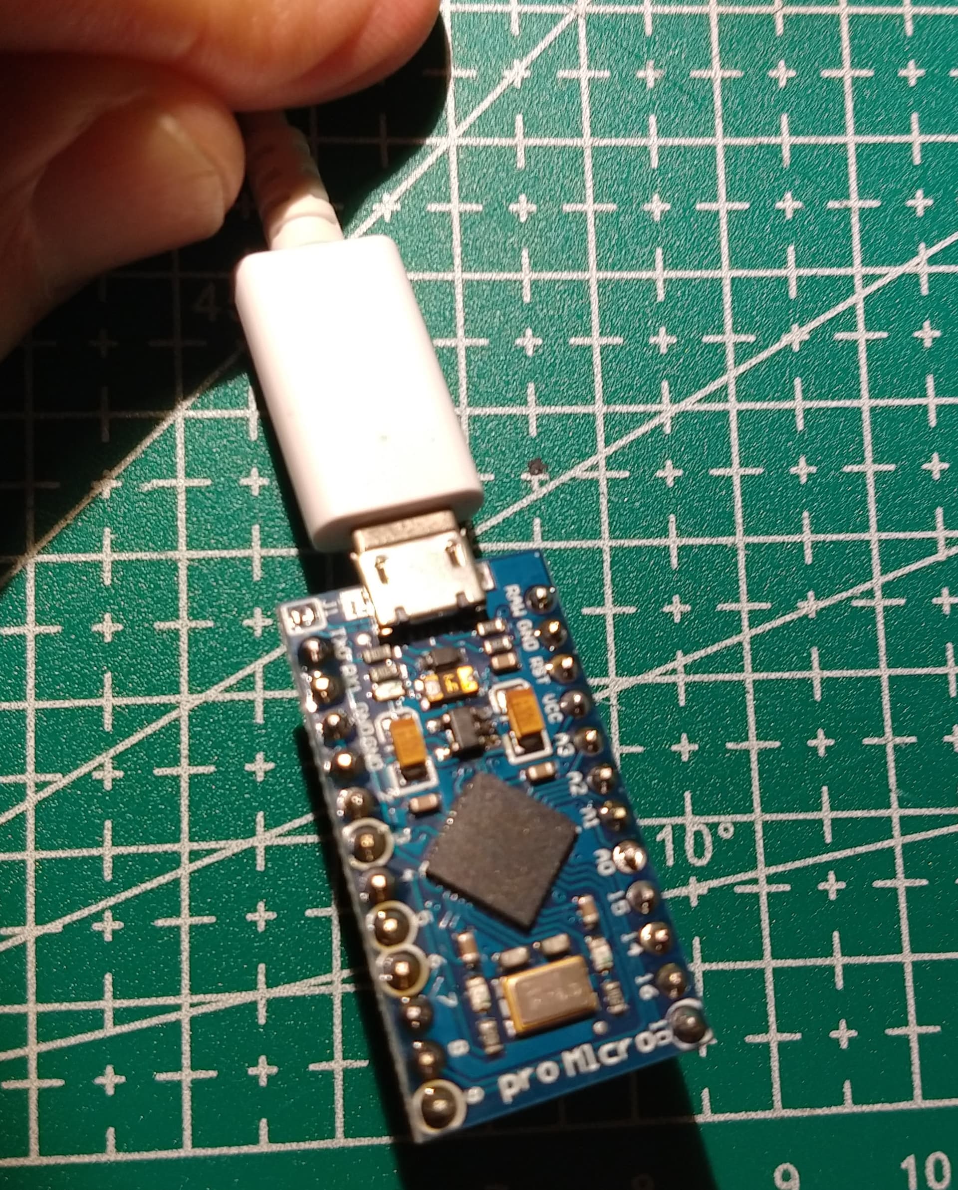
In the photo below, the blue circle is around the 12V to 5V regulator.
The arrow pointing to the component marked "F" I believe is a overcurrent device (PTC)
connected the 12 volts CC regulated power
Please describe the power source. Technically a CC regulated source will regulate the current not the voltage.
Do you have a multimeter / volt meter? If not you should consider getting one. You don't need an expensive one. Look on Amazon and find one that has a lot of good reviews. You should be able to get one between $15 and $30.
The part that gets hot is the microcontroller chip.
My regulated CC source gives a stable 12 volts and max 1 amp current. The atmega32U4 gets too hot even if it is powered from the USB with its 5 volts. Before my try with the 12 volts power source it used to not happen.
I made a similar circuit with an Arduino nano but it lacks the USB direct connection support and that is why i tried to do the same circuit with the one you put the picture.
When i connected both power sources, USB and 12 volts, I did like this: USB from the PC cable and 12 volts from the source into the opamps positive and negative pins.
In that occasion the Arduino Pro micro module got sick but it appears to be alive lighting two leds but indicates nothing when i type dmesg command at the console. So, apparently it is dead. Some kind of hot zombie.
I forgot to mention that the voltage regulator appears to be dead. It receives 4.68 volts form the diode and gives 0.2 volts at the output pin. I soldered the j1 gap and connected the module to one mobile charger and the power led lits but the atmega chip gets very hot!
As I mentioned in my JohnRob reply I wanted to reproduce a circuit i made previously with an Arduino nano. I didnt draw my own schematics but i "adapted" this circuit that i have found on OSHWLAB's site ( https://oshwlab.com/technoplusnl/midi2cv )
I think i can reproduce it here since it claims to be a Open Source Hardware Lab.
I substituted Arduino nano with Arduino Pro micro or a Arduino Leonardo's clone, the DAC chips were MCP4725 and the opamp a LM385.
The time i burnt the second one I conected the 12 volts to the raw pin of the Arduino and the opamps power pins. The MCP4725 was powered by the Arduino's VCC pin and all connected to ground.
Now i am thinking that i forget some ground connection o that i missed one pin... I only have one more Arduino to use and that is why i am asking for help, I don't want to waste my last bullet...
I don't want to appear to be stuck on this but so far no cause has been identified.
Can you give a name & model number of your 12V supply. Or maybe a link.
CC stands for constant current in nearly every power supply I've come across. If you google "CC power supply" you will get hits for a supply that can vary voltage to maintain a constant current.