Hi,
I ve desinged my own arduno micro based PCB which wirks perfectly when USB (or otherwise 5V) powered. However, when supplied with 3.3V the MPU wont run eventhough the oscillator is still working.
Please also note that I have tried powering an original arduino micro with 3.3V and it works fine. Could this be a fuse burning issue? Both arduinos are fitted with 16Mhz oscillator and I have burned the bootloader from the IDE .
Your schematic is incomplete and crucial parts of the power supply are missing.
I'm surprised you could measure this; most of the times I tried the load of the scope was enough to kill the oscillator.
What voltages do you measure in which places on your board?
Correct. Look at the data sheet for the processor, you can't run it at 3V3 and 16KHz.
Thanks for the reply.
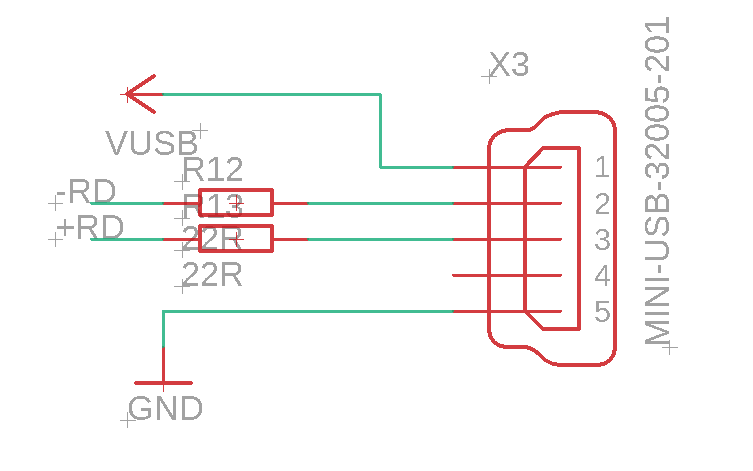
I guess the only part missing is the USB input shown below.
There will be a SMPS later but i havent built that yet trying to get everything working so far.
I ve never had problems detecting the oscillations on my scope..
I ve measured 3.3V across all decoupling caps . If other voltages are needed I d be happy to measure them
I know that at 3V3 it can only support 8 Mhz. However another 2 clone micros I ve tried work fine without changing the crystal. One of these it even has a voltage selection jumper to switch between the two voltages
That is irrelevant. Any specific processor might function outside the data sheet's specification. But it doesn't mean they all will.
You are right.
So if I just replace the crustal with an 8Mhz one, it will just work ?
Well, it doesnt.
I just replaced the crystal with an 8 Mhz one. Still works at 5V but not at 3V3. In fact it works down to around 3V8 (as it did with an 16Mhz Crystal).
So it must be something else...
Can we have a look at the complete schematic?
(Btw, there's some odd things in your schematic that I can't quite explain, but that look fairly harmless, such as C1 + C2 (why not 1x220nF or just a single 100nF which would be adequate), R7 and R8 which serve no clear function. But like I said, that doesn't explain this problem.)
C1 and C2 are decoupling capacitors each connected near each of the VCC pins of the MPU. Its not the same as having a single 200nF cap.
R7 is used for the 1-Wire devices for parasetic power.
R8 pulls down pin PE2 for compatibility with another bootloader . Can be igonred for now
Here's the complete schematic. Only thing is that regulator IC3 is shown the wrong way round but it has been corrected.
Most other parts of the schematic have been tested and work.
My apologies, the way it was drawn I mistook them for part of an RC filter to bring up RST slowly to prevent problems during startup.
Let me have a look at your full schematic...
...ok sorry to bother you again, but can you poster a higher resolution image? I can't read the text on this one at all.
Hmm.. not sure how to do higher res one.
Best I can do is print it in PDF. Hope it helps...
SBUS SENSOR MODULE V1.pdf (32.9 KB)
That's perfect, thanks 
Edit...actually not so much; the text didn't translate to the pdf properly. Check it out, it's all garbled.
Just noticed some of the text didnt print correctly on the PDF, must be an font issue..
well.. the other thing i can do is actually post the EAGLE sch file if you are familiar with EAGLE..
SBUS SENSOR MODULE V1.zip (154.4 KB)
ok..will have to try that later
Have you changed the fuses to tell it is a 8 MHz crystal?
But fuses are programmed during bootloader burning.
How can i change the afterwards?
There is no alternate setting in the IDE bootloader burning for 3v3 operation
What are the current fuse values? When you burned the bootloader, what board did you select in the IDE to burn it as? When you say it doesn't work at 3.3V, what does that mean?