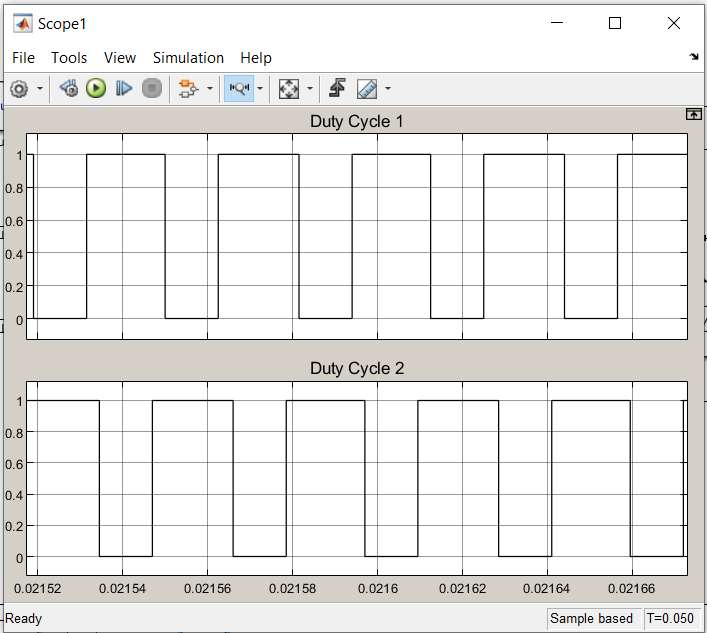
I need to produce two PWM signals from an Uno at 32kHz on pins 9 and 10. The signals need to be 180 degrees apart. Control for the duty cycle is from A1. The attached images show what I need, as an example, at 30% and 60% duty cycle.

Looks like a job for WGM mode 8 on timer 1:
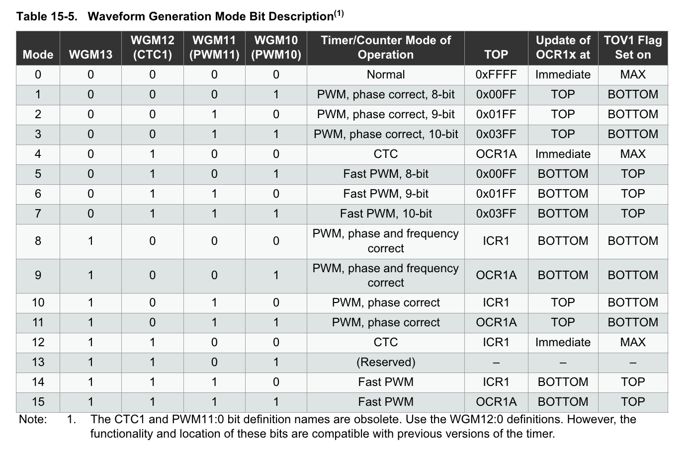
You set the frequency with ICR1, do the 180 degrees apart/inversion by setting the TCCR1A COMnx bits appropriately, and do the duty cycles with OCR1A and OCR1B.
2 Likes
I have tried to write a program to perform these PWM signals using Timer 1 but don't understand enough to be able to do it.
What code have you written? And what problems does it have?
Here's a 1Hz Mode 8 using NickGammon's TimerHelpers.h with a 25% complimentary duty cycle:
#include "TimerHelpers.h" // https://www.gammon.com.au/forum/?id=11504
// for https://forum.arduino.cc/t/two-pwm-signals-on-pins-9-and-10-with-input-on-a1-signals-need-to-be-180-degrees-apart/1280072/4?u=davex

void setup() {
  pinMode(9, OUTPUT);
  pinMode(10, OUTPUT);

  TCCR1A = 0;        // reset timer 1
  TCCR1B = 0;
  // set up Timer 1
  Timer1::setMode (8, Timer1::PRESCALE_256, Timer1::CLEAR_B_ON_COMPARE | Timer1::SET_A_ON_COMPARE);
  ICR1 = 31250; // 1Hz  Sets frequency with prescaler as f=F_CPU/PRESCALE/ICR/2
  TCNT1 = 0;         // reset counter
  OCR1A =  ICR1/4;       // compare A register value
  OCR1B =  ICR1/4;       // compare A register value

  Serial.begin(115200);
  Serial.print("TCCR1A:0b");
  Serial.println(TCCR1A,BIN);
  Serial.print("TCCR1B:0b");
  Serial.println(TCCR1B,BIN);
  Serial.print("ICR1:");
  Serial.println(ICR1);
  Serial.print("OCR1A:");
  Serial.println(OCR1A);
  Serial.print("OCR1B:");
  Serial.println(OCR1B);
  Serial.print("Freq:");
  Serial.println(F_CPU/256.0/ICR1/2,4);
}

void loop() {
}
As I said I have not been very successful writing my own code. I thought I would give ChatGP a go and this is what it produced.
const int analogPin = A1; // Input pin for analog signal

void setup() {
  // Set pins 9 and 10 as outputs
  pinMode(9, OUTPUT);
  pinMode(10, OUTPUT);

  // Configure Timer 1 for 32kHz PWM
  TCCR1A = 0; // Clear control register A
  TCCR1B = 0; // Clear control register B

  // Set Fast PWM mode with ICR1 as TOP
  TCCR1B |= (1 << WGM13) | (1 << WGM12);
  TCCR1A |= (1 << WGM11);

  // Set non-inverting mode for pin 9 and inverting mode for pin 10
  TCCR1A |= (1 << COM1A1) | (1 << COM1B1) | (1 << COM1B0);

  // Set prescaler to 1 for 32kHz frequency
  TCCR1B |= (1 << CS10);

  // Set TOP value for 32kHz PWM frequency
  ICR1 = 499; // 16MHz / (32kHz * 1) - 1

  // Start with 50% duty cycle
  OCR1A = 250;
  OCR1B = 250;
}

void loop() {
  // Read analog input from pin A1
  int analogValue = analogRead(analogPin);

  // Map analog input value (0-1023) to duty cycle (0-499)
  int dutyCycle = map(analogValue, 0, 1023, 0, 499);

  // Set duty cycle for pin 9 and pin 10
  OCR1A = dutyCycle;
  OCR1B = dutyCycle;
}
It is not correct, but its closer than I got myself. The 30% and 60% (approx) duty cycles are in the images.


I know it isn't using pins 9 and 10, but the Adafruit 16 channel PWM module can do what you want.
Try this
// UNO atmega328p

#include <avr/io.h>
#include <avr/interrupt.h>

//---------------------------
// Interrup Service Routines
// To PWM LED for debugging

ISR(TIMER1_COMPA_vect)
{
  PORTB &= ~_BV(PB5);
}

ISR(TIMER1_OVF_vect)
{
  PORTB |= _BV(PB5);
}
//---------------------------

void setup()
{
	// Set-up GPIOs
  DDRB |= _BV(PB5); // LED
  DDRB |= _BV(PB1); // OC1A output pin 9
  DDRB |= _BV(PB2); // OC1B output pin 10
  PORTB &= ~ _BV(PB5); // Turn off LED

	// Set-up Timer 1 for PWM
	// ICR1H and ICR1L – Input Capture Register 1 (NOT used)
	// Fast PWM mode 6, prescaler = 1
	// output on OC1A, inverted on OC1B

	TCCR1A = 0b10110010; // COM1A1 COM1A0 COM1B1 COM1B0 0 0 WGM11 WGM10
	TCCR1B = 0b00001001; // ICNC1 ICES1 0 WGM13 WGM12 CS12 CS11 CS10
	TCCR1C = 0;
	OCR1A = 128;
	OCR1B = 128;
	TCNT1 = 0;
  // Enable interrupts to PWM the LED (for debugging)
  // Delete if not wanted
  TIMSK1 |= (_BV(OCIE1A) | _BV(TOIE1)); // Interrupt Mask Register
  // TIFR1 = 0x00; // Interrupt Flag Register

}

void loop()
{
  // Change the PWM Duty Cycle
  for (int i=1; i<512; i++)
  {
    OCR1A = i;
    OCR1B = i;
    delay(5);
  }

}Is it not doing your duty cycle math properly?
Do you want the pin 9 signal to be 30% and the inverted out of phase signal to be 30% at the same time? Then you need to use the complementary duty cycle on the inverted signal. Maybe you need something like this completely untested snippet:
OCR1A = dutyCycle;
//  OCR1B = dutyCycle; // invert signal
OCR1B = 499-dutyCycle; // invert complimentary signal
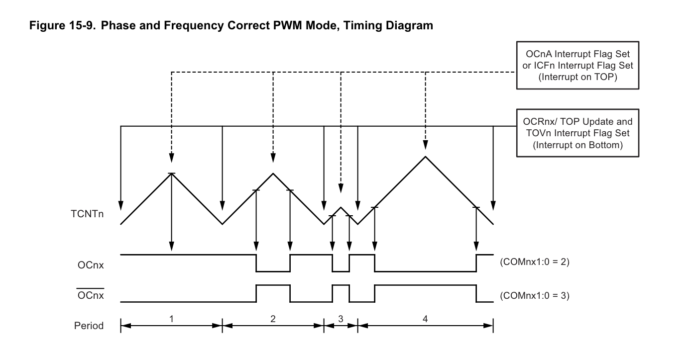
Edit: Oh. Fast PWM mode isn't going to get you the 180 degrees out of phase behavior, you'll always get two edges aligned with each other. You need this Phase and Frequency correct mode:
Here's a version for the simulation in #10 using Nick's library and a 25% duty cycle and 32kHz:
#include "TimerHelpers.h" // https://www.gammon.com.au/forum/?id=11504
// for https://forum.arduino.cc/t/two-pwm-signals-on-pins-9-and-10-with-input-on-a1-signals-need-to-be-180-degrees-apart/1280072/4?u=davex

void setup() {
  pinMode(9, OUTPUT);
  pinMode(10, OUTPUT);

  TCCR1A = 0;        // reset timer 1
  TCCR1B = 0;
  // set up Timer 1
  Timer1::setMode (8, Timer1::PRESCALE_1, Timer1::CLEAR_A_ON_COMPARE | Timer1::SET_B_ON_COMPARE);
  // ICR1 = 31250; // 31250 -> 1Hz  Sets frequency with prescaler as f=F_CPU/PRESCALE/ICR/2
    ICR1 = 250; // 250 -> 32kHz w PRESCALE_1 Sets frequency with prescaler as f=F_CPU/PRESCALE/ICR/2

  TCNT1 = 0;         // reset counter
  OCR1A =  ICR1 / 4;     // compare A register value
  //OCR1B = OCR1A;
  OCR1B =  ICR1 - OCR1A;   // compliment and invert

  Serial.begin(115200);
  Serial.print("TCCR1A:0b");
  Serial.println(TCCR1A, BIN);
  Serial.print("TCCR1B:0b");
  Serial.println(TCCR1B, BIN);
  Serial.print("ICR1:");
  Serial.println(ICR1);
  Serial.print("OCR1A:");
  Serial.println(OCR1A);
  Serial.print("OCR1B:");
  Serial.println(OCR1B);
  Serial.print("Freq:");
  Serial.println(F_CPU / 1.0 / ICR1 / 2, 4);
}

void loop() {
}
Gives:
TCCR1A:0b10110000
TCCR1B:0b10001
ICR1:250
OCR1A:62
OCR1B:188
Freq:32000.0000
If you are fiddling with the low-level timer registers you need to be very precise about what you want. One single bit can change the meaning of everything else. ChatGPT just cons you with something plausible, and can't really understand or explain why it doesn't give you the right results or use the right formulas.
Nick's TimerHelpers.h file tries to encode a lot of the datasheet complexity into nearly readable code without relying on re-reading the datasheet.
Uncle ChatGPT has given correct codes for complementary Fast PWM singals in Mode-14. The TC1 will always produce PWM signals like you have shown on the oscillogram.
Like in the #1 oscillogram? In Fast PWM Mode 14, how do you keep the signals from aligning on TCNT1==0 and to be at 180° out of phase?
Code/pix or it didn't happen.
(ChatGPT repeatedly lied to me about the frequency formulas, and then passed it off as a "communication error.")
The above formula for ICR Register given by ChatGPT in post #5 is correct.
Fast PWM is a single slope operation. The formula for frequency is:
f = 16 MHz/(N*(1+TOP)
==> TOP (ICR) = {16 MHz/(1 x 32 kHz)} - 1 = 499
ChatGPT lied to me about the dual slope formula, delivering a mish-mash of the single slope formula and a factor of 2 which I won't post here because it was wrong.
But:
The dual-slope modes seem most straightforward for keeping the phase shift at 180°. On the other hand, a fast mode with toggling might possibly work, but it also seems susceptible to initial conditions or getting out-of-whack.
Yes! Dual slope convrsion is better becuase of symmetry as we can see in Fig-1 for TC2 Phase Correct Mode-5. There is unnoticeable phase error compare to single slope Fast PWM signal.

Figure-1:
??
But how does:
...produce the oscillograms from #1?
No!
I have been referring to oscillogram of post #5.
Ah. Those are the incorrect ones:
I think OP wanted results as in #1 and with the post #5 oscillograms was showing that ChatGPT delivered the wrong timer config.
Here's some updated code for Two PWM Signals on pins 9 and 10 with input on A1. Signals Need to Be 180 degrees apart, usin NicgGammon's TimerHelpers.h, running at 1Hz with a scope and LEDs for visualization, change detection on the pot (and comments for 32kHz.)
#include "TimerHelpers.h" // https://www.gammon.com.au/forum/?id=11504
// for https://forum.arduino.cc/t/two-pwm-signals-on-pins-9-and-10-with-input-on-a1-signals-need-to-be-180-degrees-apart/1280072/4?u=davex

const unsigned long duty = 30;

void setup() {
  pinMode(9, OUTPUT);
  pinMode(10, OUTPUT);

  TCCR1A = 0;        // reset timer 1
  TCCR1B = 0;
  // set up Timer 1
  Timer1::setMode (8, Timer1::PRESCALE_256, Timer1::CLEAR_A_ON_COMPARE | Timer1::SET_B_ON_COMPARE);
  ICR1 = 31250; // 31250 -> 1Hz  Sets frequency with prescaler as f=F_CPU/PRESCALE/ICR/2
  //  ICR1 = 250; // 250 -> 32kHz w PRESCALE_1 Sets frequency with prescaler as f=F_CPU/PRESCALE/ICR/2

  TCNT1 = 0;         // reset counter
  OCR1A =  ICR1 * duty / 100;     // compare A register value
  //OCR1B = OCR1A;
  OCR1B =  ICR1 - OCR1A;   // compare B register value
  Serial.begin(115200);

  reportTimer1();
}

void loop() {
  static int lastADC = -1;
  int pot = analogRead(A0);
  if(pot != lastADC){ // change detection on potentiometer
    lastADC = pot;
    OCR1A = ICR1 * 1UL * pot/1023; // duty cycle
    OCR1B = ICR1 - OCR1A; // complement for inversion
    reportTimer1();
  }
}

void reportTimer1(void){
  Serial.print("TCCR1A:0b");
  Serial.println(TCCR1A, BIN);
  Serial.print("TCCR1B:0b");
  Serial.println(TCCR1B, BIN);
  Serial.print("ICR1:");
  Serial.println(ICR1);
  Serial.print("OCR1A:");
  Serial.println(OCR1A);
  Serial.print("OCR1B:");
  Serial.println(OCR1B);
  Serial.print("Duty:");
  Serial.println(OCR1A*100.0/ICR1,3);
  Serial.print("Freq:");
  Serial.print(F_CPU / 256.0 / ICR1 / 2, 4);
  Serial.println("Hz\n");
}
It's in Wokwi with a scope:

Would it be easier if I tried using 2 timers. Maybe then I could have independent control over both PWM signals.
Timer 1 on pin 9, and timer 2 on pin 11?
It would be harder to synchronize them and keep the 180 deg phase difference?
What don’t you like about using wgm 8/phase&freq correct mode?
1 Like
I have nothing against it, was just thinking about other approaches I could take.