Ive been trying to configure my bluetooth module to master and slave but the AT command does not appear on the Serial Monitor when i upload a blank code.Any guidance will be appreciate
alexmunala:
Ive been trying to configure my bluetooth module to master and slave but the AT command does not appear on the Serial Monitor when i upload a blank code.Any guidance will be appreciate
HC-05 is a little bit triky, there are lots of copies of that bluetooth module on the market, first you need to know that HC-05 is actually an basic serial port communication device, it communicates arduino through serial port.
I've encountered two different versions of the module so far, one of it goes AT mode without any problem and the other one has a trick to switch to AT mode.
Look backside of your module if there is STATE pin then it's easy, do the wiring as below;
VCC : 5v (older models of HC-05 were working with 3v, all the new ones works with 5v but before you connect to 5v try 3v, if led starts blinking then never connect to 5v pin, if it doesn't then connect to 5v)
GND : Ground
TXD : digital 10
RXD : digital 11
KEY : do not connect
STATE : do not connect
upload this code your arduino
#include <SoftwareSerial.h>

SoftwareSerial BTSerial(10, 11); // TX | RX

void setup()
{
  Serial.begin(9600);
  Serial.println("Waiting : ");
  BTSerial.begin(38400);
}

void loop()
{
   if (BTSerial.available())
    Serial.write(BTSerial.read());

  if (Serial.available())
    BTSerial.write(Serial.read());
}
after uploading the code, do not shutdown arduino, HC-05 has it's own CPU so it is working seperately, just disconnect the HTC-05's VCC cable, there is a tiny button on the upper left side of the module, press and hold the button, re-connect the HC-05's VCC cable while you holding tiny button on it.
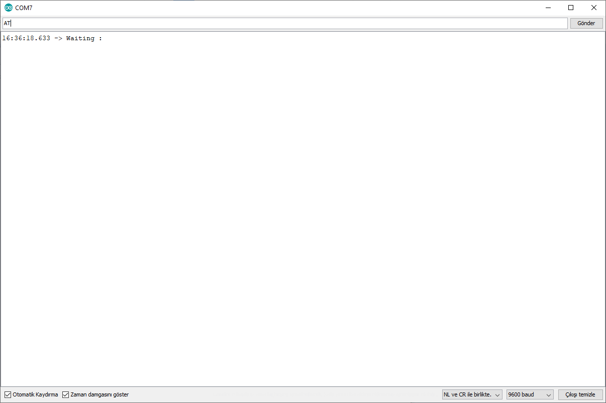
Led will start to long blinks with 2 second breaks, open terminal through arduino ide (ctrl+shift+m), your terminal settings should be "NL&CR -- 9600 baud", wait until you see "Waiting : " line, then send AT command, device will reply as OK,then you can program as you want.
To exit AT mode just disconnect the VCC,wait 5 seconds and re-connect again.
2-if you have EN pin instead of STATE :
do the wiring as below;
VCC : 5v (older models of HC-05 were working with 3v, all the new ones works with 5v but before you connect to 5v try 3v, if led starts blinking then never connect to 5v pin, if it doesn't then connect to 5v)
GND : Ground
TXD : digital 10
RXD : digital 11
KEY : do not connect
EN : digital 9
upload this code to arduino
#include <SoftwareSerial.h>

SoftwareSerial BTSerial(10, 11); // TX | RX
int STATE=9;

void setup()
{
  pinMode(9, OUTPUT);
  digitalWrite(STATE, HIGH);
  Serial.begin(9600);
  Serial.println("Waiting : ");
  BTSerial.begin(38400);
}

void loop()
{
   if (BTSerial.available())
    Serial.write(BTSerial.read());

  if (Serial.available())
    BTSerial.write(Serial.read());
}
repeat the same procedure as i mentioned for 1st version to enter AT mode, after you complete your programming you can disconnect the EN pin,it's only using to enter AT mode.
Some of chinese versions of this module's baud rate programming as 9600 on the factory but it fails to communicate with 9600, somehow those types can communicate 38400 only, when you send command from your phone,pc or any device module couldn't communicate due to wrong baud rate.
If you see characters like "xx?" when you open terminal and send command to module then it means that your module is one of them ![]() to fix it, switch to AT mode and run this command;
to fix it, switch to AT mode and run this command;
AT+UART=38400,0,0
Sorry i couldn't share photo or schematics because i'm at work.
sheshman:
HC-05 is a little bit triky, there are lots of copies of that bluetooth module on the market, first you need to know that HC-05 is actually an basic serial port communication device, it communicates arduino through serial port.I've encountered two different versions of the module so far, one of it goes AT mode without any problem and the other one has a trick to switch to AT mode.
Look backside of your module if there is STATE pin then it's easy, do the wiring as below;
VCC : 5v (older models of HC-05 were working with 3v, all the new ones works with 5v but before you connect to 5v try 3v, if led starts blinking then never connect to 5v pin, if it doesn't then connect to 5v)
GND : Ground
TXD : digital 10
RXD : digital 11
KEY : do not connect
STATE : do not connect
upload this code your arduino
#include <SoftwareSerial.h>
SoftwareSerial BTSerial(10, 11); // TX | RX
void setup()
{
Serial.begin(9600);
Serial.println("Waiting : ");
BTSerial.begin(38400);
}
void loop()
{
if (BTSerial.available())
Serial.write(BTSerial.read());
if (Serial.available())
BTSerial.write(Serial.read());
}
after uploading the code, do not shutdown arduino, HC-05 has it's own CPU so it is working seperately, just disconnect the HTC-05's VCC cable, there is a tiny button on the upper left side of the module, press and hold the button, re-connect the HC-05's VCC cable while you holding tiny button on it.

Led will start to long blinks with 2 second breaks, open terminal through arduino ide (ctrl+shift+m), your terminal settings should be "NL&CR -- 9600 baud", wait until you see "Waiting : " line, then send AT command, device will reply as OK,then you can program as you want.

To exit AT mode just disconnect the VCC,wait 5 seconds and re-connect again.

2-if you have EN pin instead of STATE :

do the wiring as below;

VCC : 5v (older models of HC-05 were working with 3v, all the new ones works with 5v but before you connect to 5v try 3v, if led starts blinking then never connect to 5v pin, if it doesn't then connect to 5v)

GND : Ground

TXD : digital 10

RXD : digital 11

KEY : do not connect

EN : digital 9

upload this code to arduino
#include <SoftwareSerial.h>
SoftwareSerial BTSerial(10, 11); // TX | RX
int STATE=9;
void setup()
{
pinMode(9, OUTPUT);
digitalWrite(STATE, HIGH);
Serial.begin(9600);
Serial.println("Waiting : ");
BTSerial.begin(38400);
}
void loop()
{
if (BTSerial.available())
Serial.write(BTSerial.read());
if (Serial.available())
BTSerial.write(Serial.read());
}
repeat the same procedure as i mentioned for 1st version to enter AT mode, after you complete your programming you can disconnect the EN pin,it's only using to enter AT mode.

Some of chinese versions of this module's baud rate programming as 9600 on the factory but it fails to communicate with 9600, somehow those types can communicate 38400 only, when you send command from your phone,pc or any device module couldn't communicate due to wrong baud rate.

If you see characters like "xx?" when you open terminal and send command to module then it means that your module is one of them :) to fix it, switch to AT mode and run this command;
AT+UART=38400,0,0
Sorry i couldn't share photo or schematics because i'm at work.
Nothing happens after the procedure.I have also noted that u mentioned that the module should have either STATE pin or EN pic.I have observed that my module has both STATE and EN pins.Is that normal or any other procedure required?
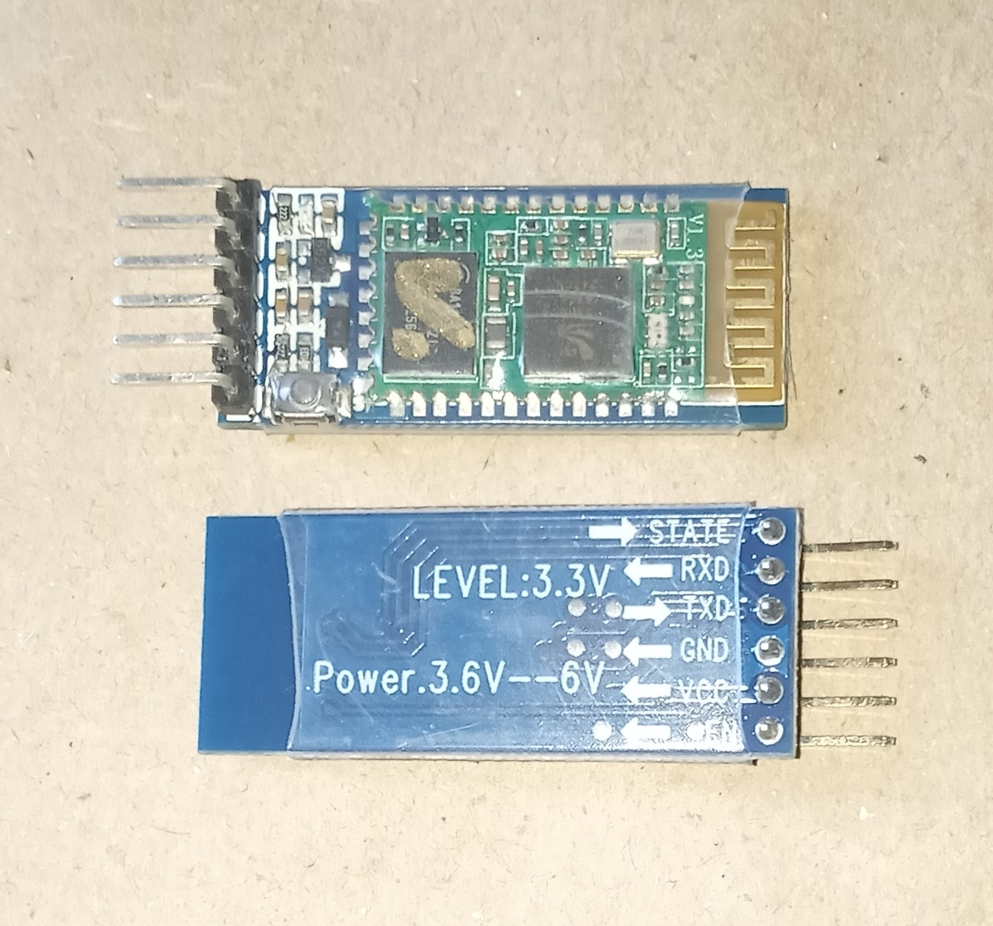
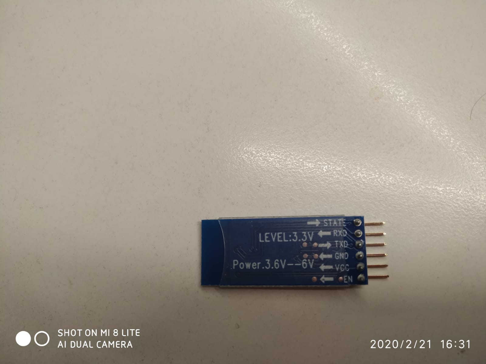
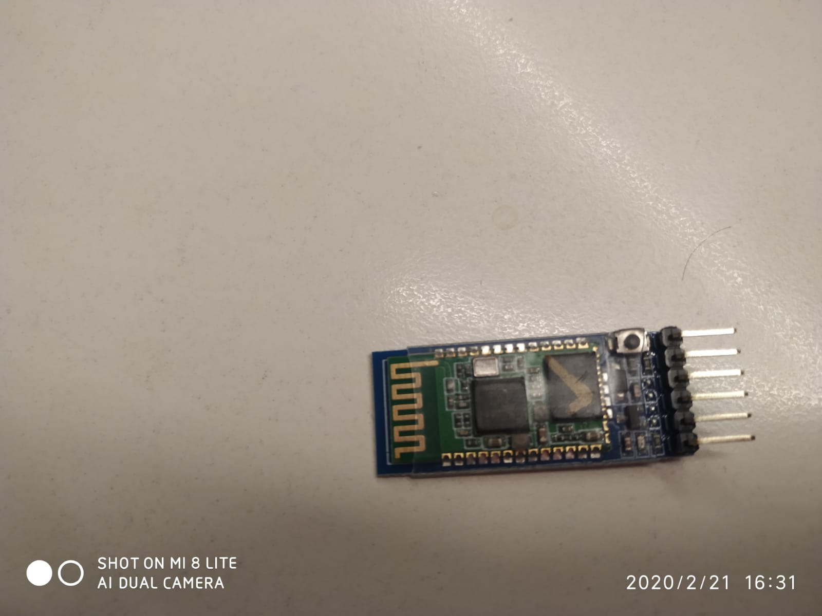
Correction : there are two different modules of HC-05 one has KEY pin other has EN pin, let me check my toolbox if i have one i'll share pictures for connections.
sheshman:
Correction : there are two different modules of HC-05 one has KEY pin other has EN pin, let me check my toolbox if i have one i'll share pictures for connections.
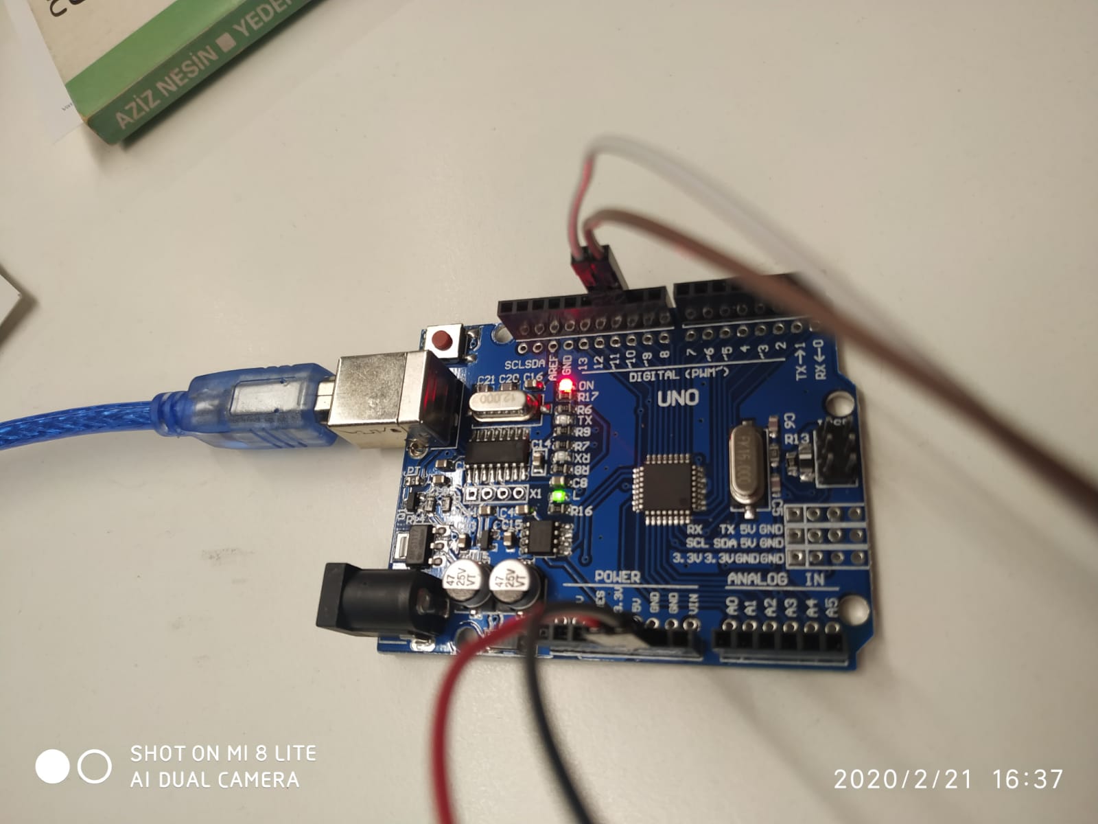
Please compare with this one that i got.


please do not change anything about my example, just try with defaults, you are using 14-15 which are RX-TX pins,it won't work with those pins, older models of HC-05 were working on RX-TX pins but new ones uses digital pins.
PS: you don't need to quote everytime you reply ![]()
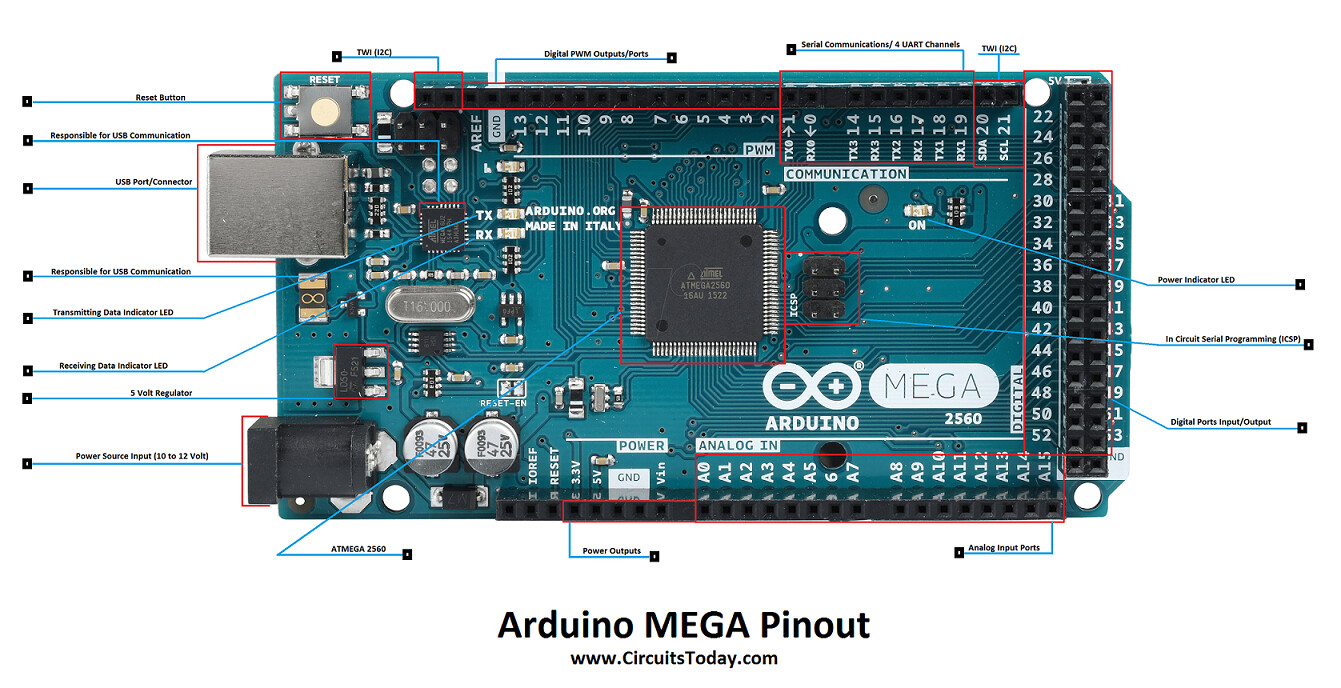
arduino MEGA is expanded version of UNO, for peoples who needs extra pins, 1,0,14,15,16,17,18,19 are for serial port communication, you can not use those pins for digital communication.
Please take a look at this :
sheshman:
please do not change anything about my example, just try with defaults, you are using 14-15 which are RX-TX pins,it won't work with those pins, older models of HC-05 were working on RX-TX pins but new ones uses digital pins.PS: you don't need to quote everytime you reply
I dont understand that...
alexmunala:
I dont understand that...
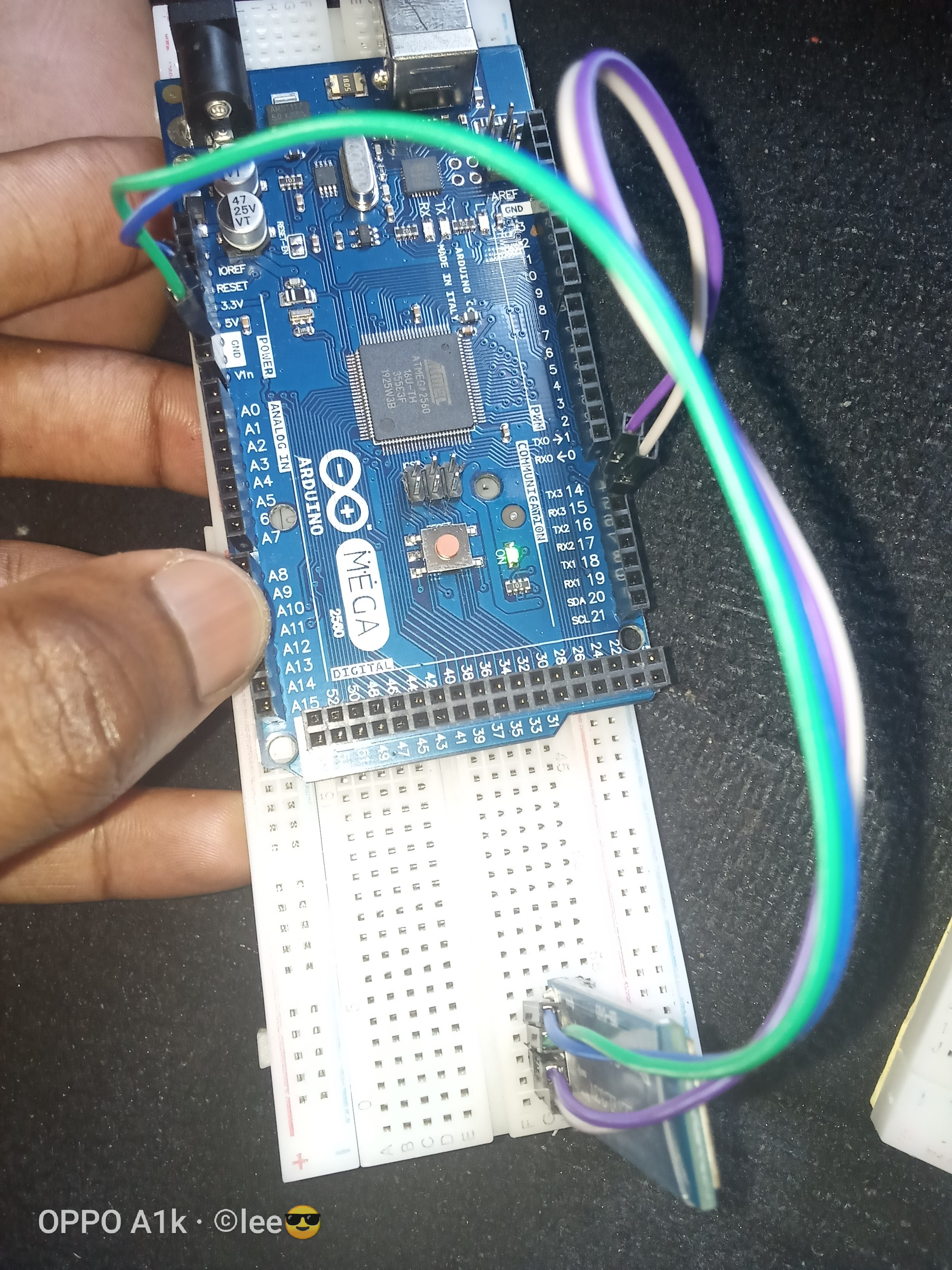
you connected RX-TX to 14-15 on your arduino MEGA, on arduino MEGA "1,0,14,15,16,17,18,19" pins for serial communication only,if you connect your RX-TX to 14-15 as you did, then module will not communicate with your arduino, just connect your module to 10-11 as i said and it will work.
Nothing still happens...There is no OK reply when I enter the AT command
sheshman:
VCC : 5v (older models of HC-05 were working with 3v, all the new ones works with 5v but before you connect to 5v try 3v, if led starts blinking then never connect to 5v pin, if it doesn't then connect to 5v)
This is nonsense. You use the voltage clearly marked on the breakout board - 3.6>6v. You will probably find that the LED will always flash if you try running it on 3.3v, or even 3v, but that doesn't mean it's a good idea, and sticking with it will very like end up being a bad one.
Nick_Pyner:
This is nonsense. You use the voltage clearly marked on the breakout board - 3.6>6v. You will probably find that the LED will always flash if you try running it on 3.3v, or even 3v, but that doesn't mean it's a good idea, and sticking with it will very like end up being a bad one.
when you connect 3v led is not blinking but nor harming the device, usually it should damage but it doesn't
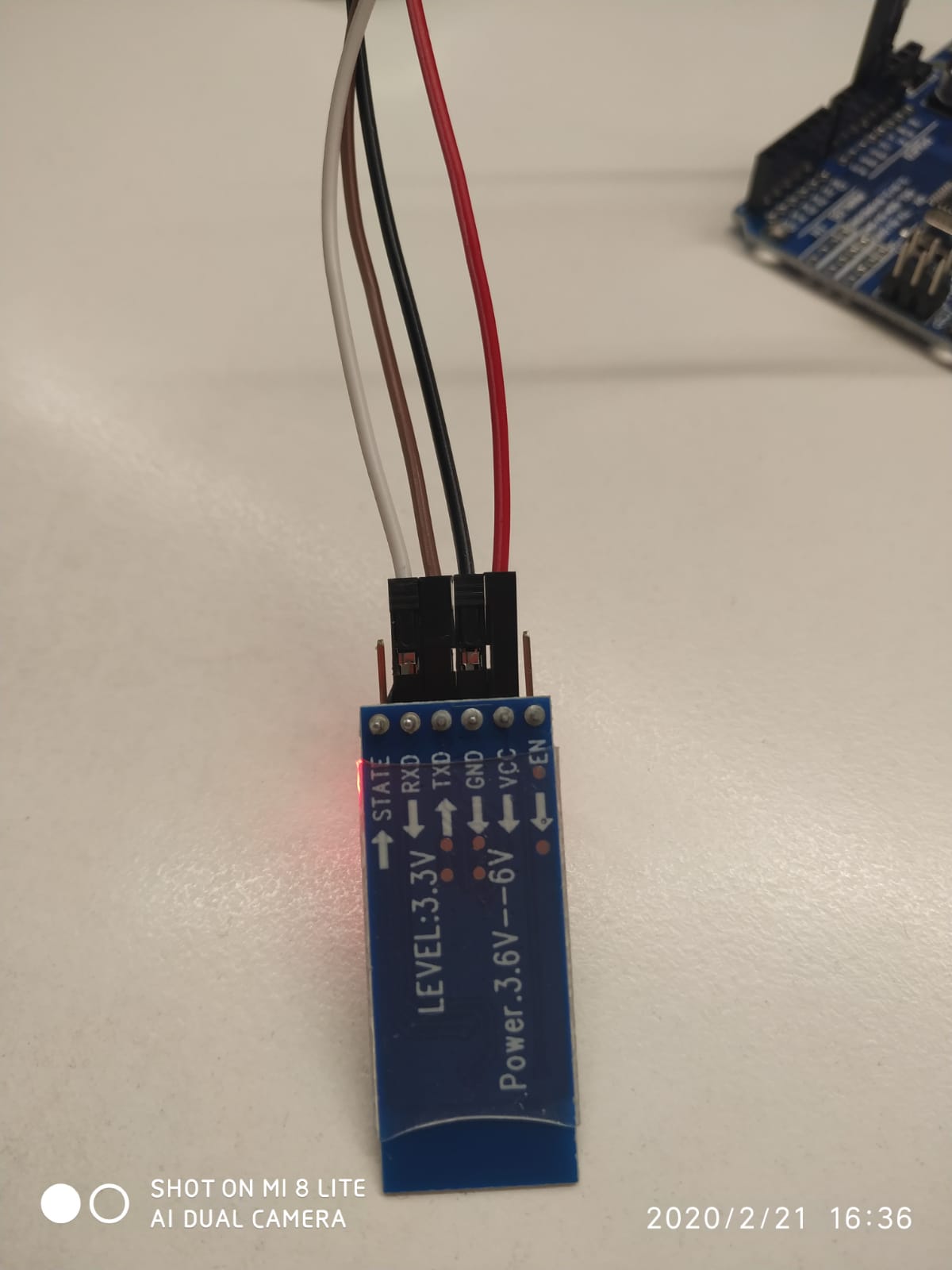
I have done the procedure to power on the module, that is, press and hold the button on the module, removed the VCC and returned it, released the button, and the light blinks once in two seconds.
I have uploaded the code but still no reply 'OK' when I enter AT mode.
void setup() {
  Serial.begin(9600);
  Serial1.begin(38400);
  Serial.println("ATcommand");  //ATcommand Start
}

void loop() {
  if (Serial1.available())
    Serial.write(Serial1.read());
  if (Serial.available())
    Serial1.write(Serial.read());
}
alexmunala:
Nothing still happens...There is no OK reply when I enter the AT command
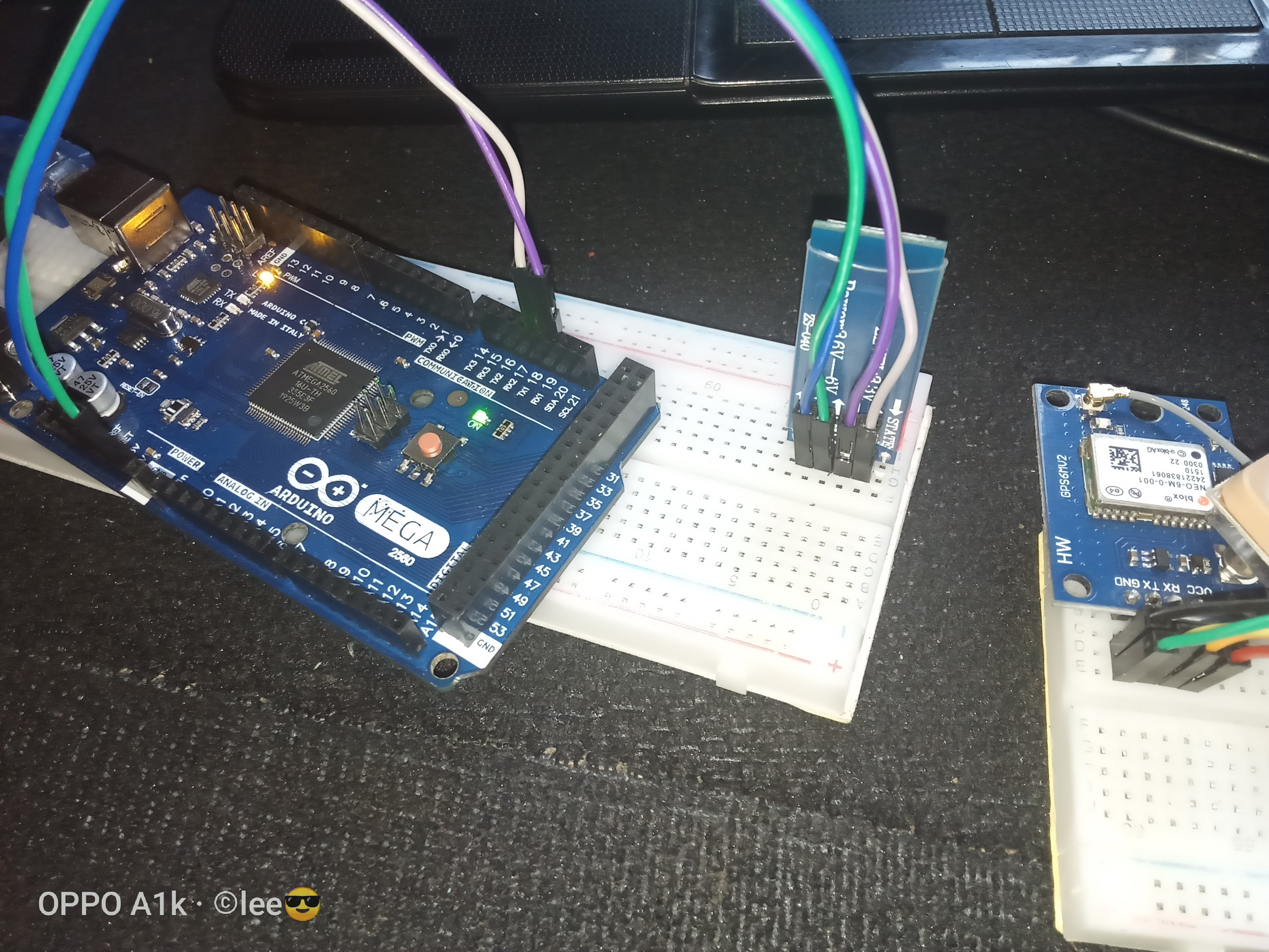
share your connection

when you connect 3v led is not blinking but nor harming the device, usually it should damage but it doesn't
Whatever floats your boat, but I just hope poor old alexmunala isn't following this incomprehensible rubbish.
@OP, you might also note that it is good practice to add a 1k/2k voltage divider in Arduino Tx line.
You should not have to go through that connection circus, simply hold the button down as you connect power to Bluetooth.
IF you are using a Mega as your code suggests, it is quite OK to use Serial1 for Bluetooth connection. Just make sure you are connected Tx>Rx and Rx>Tx. 
If you are not using a Mega, your code is not appropriate. Check the Martyn Currey website for some sensible guidance.

Nick_Pyner:
Whatever floats your boat, but I just hope poor old alexmunala isn't following this incomprehensible rubbish.@OP, you might also note that it is good practice to add a 1k/2k voltage divider in Arduino Tx line.
You should not have to go through that connection circus, simply hold the button down as you connect power to Bluetooth.
IF you are using a Mega as your code suggests, it is quite OK to use Serial1 for Bluetooth connection. Just make sure you are connected Tx>Rx and Rx>Tx.
Yes I have checked again its Rx Arduino - Tx Bt and Tx Arduino-Rx Bt