Continuing the discussion from Unable to program ATtiny84A with Arduino Nano as ISP – “Invalid device signature”:
Thank you all for your responses. These are very helpful, even if seemingly obvious solutions and replies. I am a high school biology teacher by trade, so programming and hardware are both new to me. To a novice who is exploring and still learning now to utilize Arduino technology. Thank you so much! I had never heard the word “Fritzing” before, and haphazardly tried to build a wiring diagram with TinkerCad. I didn’t realize the wiring diagram needed to be so accurate for your input. Feedback was certainly welcome. I have now downloaded the Fritzing Software and have taught myself the basics to post more accurate diagrams i hope.
Now my problem lies in powering and/or communicating with the NRF24L01 module using my ATTiny microcontroller. I have questions about powering the microcontroller, powering the NRF module, and how to achieve my goal while powering both. I am once again stuck.
I can confirm that my NRF module is alive and functional. And I can confirm that the ATTiny can successfully be programmed using the Tiny AVR programmer. However, I can’t seem to get the ATTiny slave to communicate with the master. I am using an Arduino Mega as the master. I have successfully communicated between a Mega master and a Nano slave, My code involves the polling of slaves and a response from each specific slave address after being polled to indicate to the master whether it has received a button press or not since the last poll. Basically I am building an interactive quiz buzzer system.
I have simplified my code for both the mega master and the ATTiny slave to test communication between the 2 NRF modules. However, I can’t seem to get the ATTiny to initialize the NRF module.
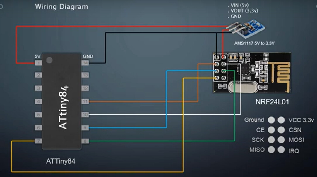
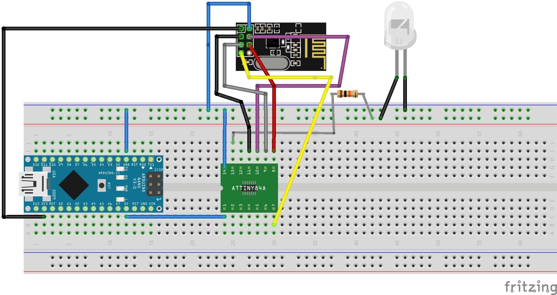
My test code is below along with the wiring diagram and my setup. The Master seems to work just fine. however my NRF module attached to the ATTiny isn’t initializing. Any advice would be invaluable.
I am currently powering the ATTiny84 using the 5v pin of the Arduino Nano. I am also powering the NRF module using the 3.3V pin of the same Arduino Nano. Is this even possible? I understand that I cannot power the NRF with 5v. I do not have a voltage divider or voltage regulator. What is the proper way to power both the ATTiny and the NRF module? Ultimately I would like to power both using batteries as this will be a wireless device. However, steps to make this battery powered will come at a later time. Right now I simply want to prototype the communication between slave and master. Ultimately I would like to configure a total of 12 slaves.
ATTiny84 code and wiring diagram is below.. When I wire everything, The LED blinks fast and the serial monitor prints radio.begin() FAILED.
#include <SPI.h>
#include <nRF24L01.h>
#include <RF24.h>

#define CE_PIN    3     // PA3, physical pin 5
#define CSN_PIN   4     // PA4, physical pin 6
#define LED_PIN   0     // PA0, physical pin 13 on ATtiny84

RF24 radio(CE_PIN, CSN_PIN);

const byte thisAddress[5] = {'S','L','V','1','A'};

unsigned long lastSendTime = 0;
const unsigned long interval = 1000;  // 1 second

void setup() {
  pinMode(LED_PIN, OUTPUT);

  Serial.begin(9600);  // Optional: only works if UART is connected
  delay(500);          // Give things time to stabilize

  if (!radio.begin()) {
    // Blink fast forever if radio fails to initialize
    while (true) {
      digitalWrite(LED_PIN, HIGH);
      delay(100);
      digitalWrite(LED_PIN, LOW);
      delay(100);
    }
  }

  radio.setDataRate(RF24_250KBPS);
  radio.setRetries(3, 5);

  radio.openWritingPipe(thisAddress);
  radio.stopListening();  // Set as transmitter
}

void loop() {
  unsigned long now = millis();

  if (now - lastSendTime >= interval) {
    lastSendTime = now;

    const char heartbeat[] = "ALIVE";
    bool sent = radio.write(&heartbeat, sizeof(heartbeat));

    // Blink LED once for success/failure
    digitalWrite(LED_PIN, HIGH);
    delay(100);
    digitalWrite(LED_PIN, LOW);

    // Optional debug output
    if (sent) {
      Serial.println("✅ Sent heartbeat");
    } else {
      Serial.println("❌ Failed to send heartbeat");
    }
  }
}